background image

Assemble the Base

15

B


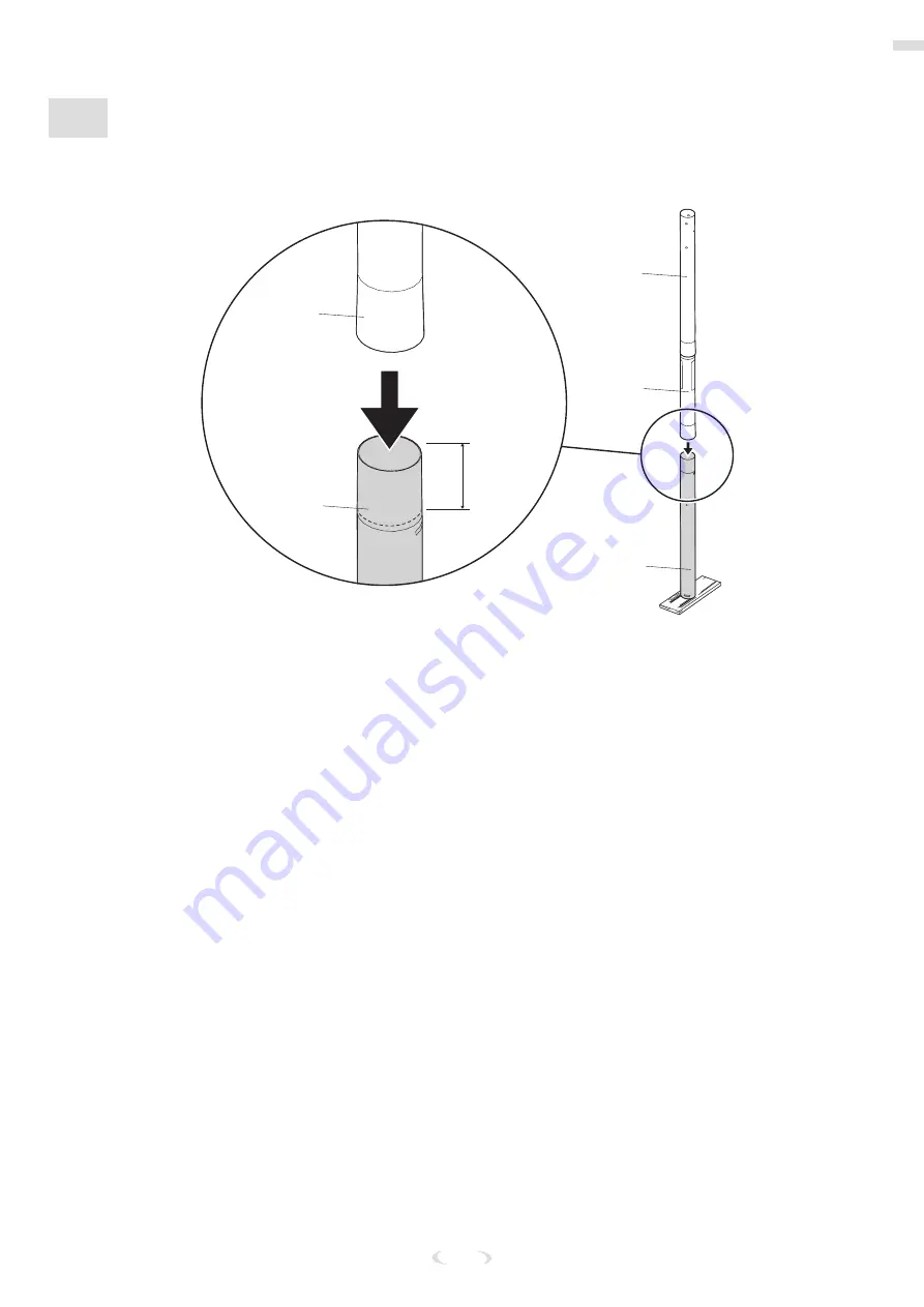
ASSEMBLE THE OVAL POLE

5. 

Align the assembled oval pole section with the bottom (6) pole section and slide together.

6. 

Bounce the assembled sections on a scrap wood board until the overlap reaches the marked line.

#6

#6

#5

#5

#4

3 1/2" 

(9 cm)

Summary of Contents for M7U6120

Page 1: ... Australia 1300 367 582 www spalding com 12 20 ID M7U6120 Model Number found on product box WARNING READ AND UNDERSTAND THE OPERATOR S MANUAL BEFORE USING THIS UNIT FAILURE TO FOLLOW THE OPERATING INSTRUCTIONS COULD RESULT IN INJURY OR DAMAGE TO PROPERTY PORTABLE BASKETBALL SYSTEM Owner s Manual ...

Page 2: ...ore Before You Begin READ AND UNDERSTAND THE OPERATOR S MANUAL BEFORE USING THIS UNIT Remove ALL contents from boxes Be sure to check INSIDE pole sections hardware and additional parts are packed inside This manual accompanied by a sales receipt should be saved and kept on hand as a convenient reference as it contains important information about your model WARNING FAILURE TO FOLLOW OPERATING INSTR...

Page 3: ... system is not installed maintained and operated properly If using a ladder during assembly use extreme caution Check the base regularly for leakage Slow leaks could cause the system to tip over unexpectedly Seat the pole sections properly if applicable Failure to do so could allow the pole sections to separate during play and or during transport of the system Climate corrosion or misuse could res...

Page 4: ...l items pictured are included with every model Package Contents Check the contents of each kit and other parts to ensure that all components are present Keep the kit hardware in the labeled bag as they will be used in different assembly steps See Parts List on page 36 for a complete list of replacement part numbers BASE ASSEMBLY 4 6 5 1 13 21 7 8 9 2 3 1 Base x1 2 Strut Left Pole to Base x1 3 Stru...

Page 5: ...x2 KIT 2 POLE TO BASE ASSEMBLY 210501 203100 NUT HEX FLANGE 5 16 18 14 24 203099Hex Locknut Nylon Insert 5 16 18 10 203153 hex head bolt 5 16 x 3 4 18 208505 22 25 12 10 Nut Ny lock 5 16 18 x1 12 Bolt Hex Head 5 16 18 x 5 0 L x1 14 Hex Flange Nut 5 16 18 x6 18 Bolt Hex Head 5 16 18 x 0 75 L x2 22 Bolt Carriage 5 16 18 x 1 50 L x6 24 Washer Flat 5 16 x4 25 Bolt Hex Head 3 8 16 x 2 L x2 POLE TO BASE...

Page 6: ...rew Jack x1 52 Handle Screw Jack x1 55 Screw Jack x1 KIT 3 ELEVATOR TO POLE ASSEMBLY 210502 203100 NUT HEX FLANGE 5 16 18 14 42 203099Hex Locknut Nylon Insert 5 16 18 10 16 20 10 Nut Ny lock 5 16 18 x1 14 Hex Flange Nut 5 16 18 x2 16 Carriage Bolt 5 16 18 x 4 50 L x2 20 Bolt Hex Head 5 16 18 x 2 75 L x1 42 Reinforcement Bracket x1 ...

Page 7: ... Upper Short x2 38 Cap Pole Top x1 40 Triangle Plates x2 54 Backboard x1 61 Board Pad Left Section x1 62 Board Pad Right Section x1 KIT 4 BACKBOARD 210503 203100 NUT HEX FLANGE 5 16 18 14 26 45 66 65 64 63 14 Hex Flange Nut 5 16 18 x4 26 Bolt Hex Flange 5 16 18 x 1 625 L x4 45 Bolt Tee 3 8 16 3 25 Long x1 63 Washer Flat 1 4 x6 64 Screw 1 4 x 1 00 Long x6 65 Protector Screw x6 66 Drill Bit 11 64 x1...

Page 8: ...t Hex Head 1 2 13 x 2 Long x4 30 Spacer Plastic 0 50 I D x 0 13 Long x4 31 Lock Nut Hex 1 2 13 x8 36 Spacer Plastic 0 53 ID x 2 38 L x2 49 Spacer 0 53 ID x 0 75 OD x 3 25 L x1 50 Spacer 0 5 ID x 0 98 OD x 1 64 L x4 COVER ASSEMBLY 56 57 58 56 Bracket Cover Left x1 57 Bracket Cover Right x1 58 Twist Latch x2 ...

Page 9: ... raise and lower backboard Do not over crank handle beyond the manufactured height indicator range of 7 1 2 10 feet Damage may be caused to the screw jack s internal adjustment mechanism if adjusted over 10 or under 7 1 2 feet A B 59 33 28 44 34 43 203617 41 34 Rim x1 28 Cover Plate Rim x1 44 Bracket Slam Jam Square Black x1 41 Cap for Base x1 33 Label Height Adjustment and Moving x1 43 Net x1 59 ...

Page 10: ...s for Assembly 2 Capable Adults Mallet Safety Glasses Socket Wrench 1 2 9 16 3 4 Socket Wrench Extension Wrench 1 2 9 16 3 4 Tape Measure Phillips Screwdriver Sawhorse Step Ladder 8 ft Scrap Wood Board Sand Garden Hose OPTIONAL Adjustable Wrenches ...

Page 11: ...ew Elevator System Section D E F G Bottom Pole Section B Top Base Section J Rim Section H Top Pole Section B Middle Pole Section B Bottom Base Section A Stadium Pad Section C Wheel Carriage Section A Struts Section C Backboard Section E F ...

Page 12: ...e Required Parts Completed Base Assembly Kit 1 Kit 2 Scrap Wood Board Socket Wrench or Wrench Mallet A ASSEMBLE THE WHEELS 1 Insert the wheels 8 into the wheel brackets 7 2 Insert the axle 9 through the wheel brackets 7 and wheels 8 9 8 7 ...

Page 13: ... 7 and wheel assembly to the base 1 with the bolts 18 and washers 24 18 24 7 1 B ASSEMBLE THE OVAL POLE 1 Identify the top 6 middle 5 and bottom 4 oval pole sections 2 Mark 3 1 2 9 cm from the top of both the middle 5 and bottom 4 pole sections 4 5 3 1 2 9 cm 3 1 2 9 cm 6 ...

Page 14: ... ENGAGEMENT OVERLAP OF 3 1 2 9 CM CANNOT BE ACHIEVED STOP DO NOT PROCEED TO THE NEXT STEP CALL SPALDING CUSTOMER SERVICE AT 1 800 558 5234 FOR ASSISTANCE 3 Align the top 4 pole section with the middle 5 pole section and slide together 4 Bounce the assembled sections on a scrap wood board until the overlap reaches the marked line 5 4 4 5 5 4 3 1 2 9 cm ...

Page 15: ...SEMBLE THE OVAL POLE 5 Align the assembled oval pole section with the bottom 6 pole section and slide together 6 Bounce the assembled sections on a scrap wood board until the overlap reaches the marked line 6 6 5 5 4 3 1 2 9 cm ...

Page 16: ...nd the pole mounting plate 19 WARNING TWO PEOPLE ARE REQUIRED FOR THIS PROCEDURE FAILURE TO FOLLOW THIS WARNING COULD RESULT IN SERIOUS INJURY AND OR PROPERTY DAMAGE 1 25 19 2 Attach the struts 2 and 3 to the middle pole 5 with the bolt 12 washers 24 and nuts 10 IMPORTANT DO NOT TIGHTEN COMPLETELY 10 2 24 24 3 5 12 ...

Page 17: ...s 2 and 3 to align with the mounting holes in the base 1 4 Secure the ends of the base struts 2 and 3 to the base frame using bolts 18 and lock washers 24 IMPORTANT TIGHTEN ALL COMPONENTS COMPLETELY 18 2 3 1 24 5 Secure the cover 21 to the base struts 2 and 3 using the bolts 22 and nuts 14 21 22 3 14 2 ...

Page 18: ...Parts Completed Elevator Assembly Kit 3 Socket Wrench or Wrench D INSTALL THE ELEVATOR ASSEMBLY 1 Securely rest the assembly on a sawhorse 2 Slide the screw jack sleeve 17 over the screw jack assembly 55 and attach the cap 51 to the top end 51 17 55 ...

Page 19: ...ole mount bracket 15 and the reinforcement bracket 42 to the middle pole 5 using the carriage bolts 16 and flange nuts 14 4 Tighten the flange nuts 14 completely 5 14 16 42 15 5 Attach the screw jack sleeve 17 to the pole bracket 15 using bolt 20 and nut 10 15 20 17 10 ...

Page 20: ...Elevator Assembly 20 D INSTALL THE ELEVATOR ASSEMBLY 6 Attach the handle 52 to the screw jack with the pin 27 52 27 ...

Page 21: ...r Socket Wrenches Socket Wrench Extension Phillips Screwdriver Sawhorse WARNING TWO PEOPLE ARE REQUIRED FOR THIS PROCEDURE FAILURE TO FOLLOW THIS WARNING COULD RESULT IN SERIOUS INJURY AND OR PROPERTY DAMAGE E ATTACH THE ELEVATOR TUBE ASSEMBLY 1 Securely rest the assembly on a sawhorse Identify the elevator tubes 32 and 35 32 35 ...

Page 22: ...Install pole cap 38 at this time WARNING TIGHTEN THE BOLTS 11 AND 29 IN THE LOCK NUTS 31 UNTIL FLUSH EVEN WITH THE LOCK NUT S OUTER EDGE NOTE TEST FIT THE LARGE BOLTS INTO THE LARGE HOLES OF THE ELEVATOR TUBES BACKBOARD BRACKETS AND TRIANGLE PLATES CAREFULLY ROCK THEM IN A CIRCULAR MOTION TO REAM OUT ANY EXCESS PAINT FROM HOLES IF NECESSARY 29 29 11 38 50 31 49 40 50 35 32 31 ...

Page 23: ...he elevator tubes 32 35 to the backboard using the spacers 30 bolts 23 and nuts 31 35 31 32 30 23 2 Insert the t bolt 45 into the slam jam bracket 44 and attach to board using the bolts 26 and nuts 14 IMPORTANT CAREFULLY CUT AND PEEL PROTECTIVE FILM AWAY FROM BOARD PRIOR TO ATTACHING RIM 26 44 45 14 ...

Page 24: ...Assemble the Upper Elevator 24 G ATTACH THE ELEVATOR ASSEMBLY 1 Attach the handle assembly 55 to the lower elevator tubes 32 using the bolt 29 spacers 36 and nut 31 29 32 31 55 36 ...

Page 25: ...Completed Goal Assembly Kit 6 Wrenches and or Socket Wrenches Socket Wrench Extension Phillips Screwdriver H ASSEMBLE THE GOAL 1 Fit the rim 34 securely into the slam jam bracket 44 Allow the t bolt 45 to slip through the center hole in the rim 34 45 34 44 ...

Page 26: ...Assemble the Goal 26 H ASSEMBLE THE GOAL 2 Install the reinforcement bracket 46 onto the t bolt 45 45 46 3 Install the spring 47 onto the t bolt 45 45 47 ...

Page 27: ...le the Goal 27 H ASSEMBLE THE GOAL 4 Install the special nut 48 and washer 37 onto the t bolt 45 37 48 45 5 Tighten the nut 48 until 1 8 of the bolt threads onto the exposed end of the t bolt 45 45 48 1 8 3mm ...

Page 28: ...Assemble the Goal 28 H ASSEMBLE THE GOAL 6 Install the rim cover using the cover screws 28 39 34 7 Thread the net 43 onto the rim 34 34 34 34 34 43 43 43 43 ...

Page 29: ...1 2 3 4 5 Checksystem for stability 4 2 1 3 Rotate crank handle to raise and lower backboard Do not over crank handle beyond the manufactured height indicator range of 7 1 2 10 feet Damage may be caused to the screw jack s internal adjustment mechanism if adjusted over 10 or under 7 1 2 feet A B 33 9 Apply the Height Indicator Labels 53 to the screw jack 10 Adjust the height to 7 1 2 feet 2 3 m fr...

Page 30: ... slightly if necessary It may be necessary to trim away some material to achieve a proper fit around the goal and supports 2 Using a 5 16 socket wrench or portable drill with a 5 16 socket attachment with the torque adjustment at the lowest setting fasten the edge guards in place with the provided self drilling self tapping screws 64 3 If the ends of the screws are exposed after installation place...

Page 31: ... TO FOLLOW THIS WARNING COULD RESULT IN SERIOUS INJURY DO NOT LEAVE THE ASSEMBLY UNATTENDED WHEN EMPTY IT MAY TIP OVER FAILURE TO FOLLOW THIS WARNING COULD RESULT IN SERIOUS INJURY AND OR PROPERTY DAMAGE THE CAP 33 MUST BE TIGHTENED COMPLETELY AND SECURELY TO PREVENT LEAKAGE CONTACT CUSTOMER SERVICE IMMEDIATELY IF THE CAP IS MISSING OR DAMAGED CHECK THE WATER LEVEL BEFORE EACH USE ...

Page 32: ...VER 1 Mount the cover brackets 56 57 to the base Secure the cover using bolts 60 washers 24 and nuts 14 56 60 24 57 14 2 Roll completed assembly to desired position Fill the base with water approx 19 gallons 71 Liters and place the cap 41 into base 1 41 ...

Page 33: ...e 33 J INSTALL THE COVER 3 Place four 50 lb 23 kg sand or cement mix bags into the base 1 cavity 1 4 Install cover 13 to base 1 and snap into place 5 Use twist latches 58 to secure cover 13 to cover mount brackets 56 and 57 13 57 58 ...

Page 34: ...Fill The Assembled Unit For Use 34 J INSTALL THE COVER 6 Fill cover 13 with water approx 1 gallons 3 8 Liters Tighten cap 59 securely into place 59 ...

Page 35: ...RANK THE HANDLE BEYOND THE HEIGHT INDICATOR RANGE OF 7 1 2 TO 10 FEET OR THE ADJUSTMENT MECHANISM MAY BE DAMAGED L MOVING THE UNIT 1 Adjust the basketball backboard height to the lowest postion 2 Rotate the handle forward until the wheels engage the ground 3 Move the basketball system to the desired location 4 Rotate the handle back to its original position 5 Check the system for stability ...

Page 36: ...rts List 62 39 43 6 4 33 2 3 18 24 61 46 64 63 54 47 26 65 34 48 28 44 14 19 25 38 5 14 10 17 55 53 51 29 36 50 32 31 50 31 30 35 23 40 49 11 52 27 59 41 1 57 15 20 21 22 14 13 18 56 60 24 58 14 24 7 8 9 10 24 12 16 42 ...

Page 37: ...5 0 Long 37 1 203470 Washer Flat 0 625 I D x 1 5 O D 13 1 60028501 Cover Sandbase 38 1 600362 Cap Pole Top 14 14 203100 Hex Flange Nut 5 16 18 39 2 204558 Screw 1 4 x 0 375 Long 15 1 908415 Bracket Pole Mount 40 2 900867 Triangle Plates 16 2 204846 Carriage Bolt 5 16 18 x 4 50 Long 41 1 203617 Cap Base Black 17 1 60016401 Sleeve Screw Jack 42 1 209240 Reinforcement Bracket 18 4 203153 Bolt Hex Hea...

Page 38: ...ight Indicator 61 1 20157801 Board Pad Left Section 54 1 Backboard Acrylic 62 1 20157901 Board Pad Right Section 55 1 80034403 Screw Jack Assembly 63 6 206303 Washer Flat 1 4 56 1 600317 Bracket Cover Left 64 6 201538 Screw 1 4 x 1 00 Long 57 1 600318 Bracket Cover Right 65 6 202219 Protector Screw 58 2 600300 Twist Latch 66 1 205355 Drill Bit 11 64 59 1 208770 Cap Base Tan ...

Page 39: ... 39 ...

Page 40: ...l or other sharp objects Punctures cause leakage and could cause system to tip over Keep organic material away from pole base Grass litter etc could cause corrosion and or deterioration Check pole system for signs of corrosion rust pitting chipping and repaint with exterior enamel paint If rust has penetrated through the steel anywhere replace pole immediately Check system before each use for prop...

Page 41: ...S DE USAR ESTA UNIDAD EL INCUMPLIMIENTO DE LAS INSTRUCCIONES DE FUNCIONAMIENTO PODRÍA OCASIONAR LESIONES O DAÑOS MATERIALES Teléfono gratuito del servicio al cliente EE UU 1 800 558 5234 Canadá 1 800 284 8339 Europa 353 51 379777 Australia 1300 367 582 www spalding com Número de modelo se encuentra en la caja del producto ESPAÑOL ...

Page 42: ...ALTO Questions or Missing Parts Call TOLL FREE Customer Service Number listed on the front page DON T go back to store Questions or Mis Call TOLL FREE Cus Number listed on th DON T go back Antes de empezar LEA Y COMPRENDA EL MANUAL DEL OPERADOR ANTES DE USAR ESTA UNIDAD Saque TODO el contenido de las cajas Asegúrese de revisar el INTERIOR de las secciones de los postes los herrajes y las piezas ad...

Page 43: ...nstala mantiene y funciona adecuadamente Si usa una escalera durante el montaje extreme la precaución Revise regularmente la base para detectar si hay fugas Las fugas lentas pueden hacer que el sistema se vuelque inesperadamente Asiente las secciones del poste correctamente si corresponde De lo contrario las secciones del poste podrían separarse al jugar o al transportarlo El clima la corrosión o ...

Page 44: ...artículos ilustrados están incluidos en cada modelo Contenido del paquete Compruebe el contenido de cada kit y otras piezas para asegurarse de que se incluyen todas las partes Conserve los herrajes del kit en la bolsa etiquetada ya que los utilizará en diferentes pasos del montaje Vea el Listado de piezas de la página 76 para ver la lista completa de los números de las piezas de recambio MONTAJE D...

Page 45: ...E EN LA BASE 210501 203100 NUT HEX FLANGE 5 16 18 Núm 14 Núm 24 203099Hex Locknut Nylon Insert 5 16 18 Núm 10 203153 hex head bolt 5 16 x 3 4 Núm 18 208505 Núm 22 Núm 25 Núm 12 10 Tuerca Nylock 5 16 18 x1 12 Perno cabeza hexagonal 5 16 18 x 5 0 de largo x1 14 Tuerca brida hexagonal 5 16 18 x6 18 Perno cabeza hexagonal 5 16 18 x 0 75 de largo x2 22 Perno de carruaje 5 16 18 x 1 50 de largo x6 24 Ar...

Page 46: ...x1 52 Manivela elevador mecánico x1 55 Elevador mecánico x1 KIT 3 MONTAJE DEL ELEVADOR EN EL POSTE 210502 203100 NUT HEX FLANGE 5 16 18 Núm 14 Núm 42 203099Hex Locknut Nylon Insert 5 16 18 Núm 10 Núm 16 Núm 20 10 Tuerca Nylock 5 16 18 x1 14 Tuerca brida hexagonal 5 16 18 x2 16 Perno de carruaje 5 16 18 x 4 50 de largo x2 20 Perno cabeza hexagonal 5 16 18 x 2 75 de largo x1 42 Soporte de refuerzo x...

Page 47: ...38 Tapa parte superior del poste x1 40 Placas triangulares x2 54 Tablero x1 61 Almohadilla del tablero sección izquierda x1 62 Almohadilla del tablero sección derecha x1 KIT 4 TABLERO 210503 203100 NUT HEX FLANGE 5 16 18 Núm 14 Núm 26 Núm 45 Núm 66 Núm 65 Núm 64 Núm 63 14 Tuerca brida hexagonal 5 16 18 x4 26 Perno brida hexagonal 5 16 18 x 1 625 de largo x4 45 Perno en T 3 8 16 3 25 de largo x1 63...

Page 48: ...iador de plástico 0 50 d int x 0 13 de largo x4 31 Tuerca Nylock hexagonal 1 2 13 x8 36 Espaciador de plástico 0 53 d int x 2 38 de largo x2 49 Espaciador 0 53 d int x 0 75 d ext x 3 25 de largo x1 50 Espaciador 0 5 d int x 0 98 d ext x 1 64 de largo x4 MONTAJE DE LA CUBIERTA Núm 56 Núm 57 Núm 58 56 Soporte cubierta izquierdo x1 57 Soporte cubierta derecho x1 58 Pestillo giratorio x2 ...

Page 49: ...ja 2 Mientras sujeta el poste gire el sistema de baloncesto hacia adelante hasta que las ruedas toquen el suelo 3 Mueva el sistema de baloncesto hasta la ubicación deseada 4 Con cuidado vuelva a poner el sistema de baloncesto en posición vertical 5 Compruebe que el sistema está estable Núm 59 Núm 33 Núm 28 Núm 44 Núm 34 Núm 43 203617 Núm 41 34 Aro x1 28 Placa de cubierta aro x1 44 Soporte Slam Jam...

Page 50: ...aje 2 adultos capaces Mazo Gafas de seguridad Llave de vaso 1 2 9 16 3 4 Extensión de llave de vaso Llave 1 2 9 16 3 4 A R E N A Cinta métrica Destornillador de estrella Caballete Escalera de mano 8 pies Tabla de madera de desecho Manguera de jardín o arena OPCIONAL Llaves ajustables ...

Page 51: ... Secciones D E F G Poste inferior Sección B Base superior Sección J Aro Sección H Poste superior Sección B Poste intermedio Sección B Base inferior Sección A Cubierta estilo cancha Sección C Soporte con ruedas Sección A Puntales Sección C Tablero Secciones E F ...

Page 52: ... completo de la base Kit 1 Kit 2 Tabla de madera de desecho Llave de vaso o llave Mazo A MONTAJE DE LAS RUEDAS 1 Introduzca las ruedas 8 en los soportes de las ruedas 7 2 Introduzca el eje 9 a través de los soportes de las ruedas 7 y de las ruedas 8 Núm 9 Núm 8 Núm 7 ...

Page 53: ... 1 con los pernos 18 y las arandelas 24 Núm 18 Núm 24 Núm 7 Núm 1 B MONTAJE DEL POSTE OVALADO 1 Identifique la sección superior 6 intermedia 5 e inferior 4 del poste ovalado 2 Marque 3 1 2 9 cm desde la parte superior de las secciones del poste intermedio 5 y del poste inferior 4 Núm 4 Núm 5 3 1 2 9 cm 3 1 2 9 cm Núm 6 ...

Page 54: ... SUPERPOSICIÓN DE ENGANCHE DE 3 1 2 9 CM PARE NO CONTINÚE CON EL SIGUIENTE PASO LLAME AL SERVICIO AL CLIENTE DE SPALDING AL 1 800 558 5234 PARA RECIBIR AYUDA 3 Alinee la sección superior del poste 4 con la sección intermedia del poste 5 y encájelas 4 Empuje las secciones ensambladas sobre el bloque de madera hasta que la superposición alcance la línea marcada Núm 5 Núm 4 Núm 4 Núm 5 Núm 5 Núm 4 3 ...

Page 55: ...O 5 Alinee la sección del poste ovalado montada con la sección inferior del poste 6 y encájelas 6 Empuje las secciones ensambladas sobre el bloque de madera hasta que la superposición alcance la línea marcada Núm 6 Núm 6 Núm 5 Núm 5 Núm 4 3 1 2 9 cm ...

Page 56: ...ADVERTENCIA SE REQUIEREN DOS PERSONAS PARA ESTE PROCEDIMIENTO EL INCUMPLIMIENTO DE ESTA ADVERTENCIA PODRÍA OCASIONAR LESIONES GRAVES Y O DAÑOS MATERIALES Núm 1 Núm 25 Núm 19 2 Fije los puntales 2 y 3 al poste intermedio 5 con el perno 12 las arandelas 24 y las tuercas 10 IMPORTANTE NO LO APRIETE DEL TODO Núm 10 Núm 2 Núm 24 Núm 24 Núm 3 Núm 5 Núm 12 ...

Page 57: ...ontaje de la base 1 4 Fije los extremos de los puntales de la base 2 y 3 en el marco de la base con los pernos 18 y las arandelas de seguridad 24 IMPORTANTE APRIETE COMPLETAMENTE TODAS LAS PIEZAS Núm 18 Núm 2 Núm 3 Núm 1 Núm 24 5 Fije la cubierta 21 sobre los puntales de la base 2 y 3 utilizando los pernos 22 y las tuercas 14 Núm 21 Núm 22 Núm 3 Núm 14 Núm 2 ...

Page 58: ...eto del elevador Kit 3 Llave de vaso o llave D COLOCACIÓN DEL MONTAJE DEL ELEVADOR 1 Apoye el montaje de forma segura en el caballete 2 Deslice la funda del elevador mecánico 17 por encima del elevador mecánico 55 y coloque la tapa 51 en el extremo superior Núm 51 Núm 17 Núm 55 ...

Page 59: ... de refuerzo 42 en el poste intermedio 5 utilizando los pernos de carruaje 16 y las tuercas bridadas 14 4 Apriete las tuercas bridadas 14 por completo Núm 5 Núm 14 Núm 16 Núm 42 Núm 15 5 Fije el montaje de la funda del elevador mecánico 17 al soporte del poste 15 con el perno 20 y la tuerca 10 Núm 15 Núm 20 Núm 17 Núm 10 ...

Page 60: ...Montaje del elevador 60 D COLOCACIÓN DEL MONTAJE DEL ELEVADOR 6 Fije la manivela 52 en el elevador mecánico con el pasador 27 Núm 52 Núm 27 ...

Page 61: ... de llave de vaso Destornillador de estrella Caballete ADVERTENCIA SE REQUIEREN DOS PERSONAS PARA ESTE PROCEDIMIENTO EL INCUMPLIMIENTO DE ESTA ADVERTENCIA PODRÍA OCASIONAR LESIONES GRAVES Y O DAÑOS MATERIALES E COLOCACIÓN DEL MONTAJE DEL TUBO ELEVADOR 1 Apoye el montaje de forma segura en el caballete Identifique los tubos del elevador 32 y 35 Núm 32 Núm 35 ...

Page 62: ...ERTENCIA APRIETE LOS PERNOS 11 Y 29 EN LAS CONTRATUERCAS 31 HASTA QUEDAR PAREJOS CON EL BORDE EXTERIOR DE LA CONTRATUERCA NOTA COMPRUEBE EL AJUSTE DE LOS PERNOS GRANDES EN LOS ORIFICIOS GRANDES DE LOS TUBOS DEL ELEVADOR LOS SOPORTES DEL TABLERO Y LAS PLACAS TRIANGULARES SI FUESE NECESARIO CON CUIDADO REALICE MOVIMIENTOS CIRCULARES PARA EXTRAER EL EXCESO DE PINTURA DE LOS ORIFICIOS Núm 29 Núm 29 Nú...

Page 63: ... tablero utilizando los espaciadores 30 los pernos 23 y las tuercas 31 Núm 35 Núm 31 Núm 32 Núm 30 Núm 23 2 Inserte el perno en T 45 en el soporte Slam Jam 44 y fíjelo al tablero utilizando los pernos 26 y las tuercas 14 IMPORTANTE CORTE Y DESPEGUE CON CUIDADO LA PELÍCULA PROTECTORA DEL TABLERO ANTES DE COLOCAR EL ARO Núm 26 Núm 44 Núm 45 Núm 14 ...

Page 64: ...or superior 64 G COLOCACIÓN DEL MONTAJE DEL ELEVADOR 1 Fije el montaje de la manija 55 en los tubos del elevador inferiores 32 utilizando el perno 29 los espaciadores 36 y la tuerca 31 Núm 29 Núm 32 Núm 31 Núm 55 Núm 36 ...

Page 65: ...to de la canasta Kit 6 Llaves y o llaves de vaso Extensión de llave de vaso Destornillador de estrella H MONTAJE DE LA CANASTA 1 Fije firmemente el aro 34 en el soporte slam jam 44 Deje que el perno en T 45 se deslice a través del orificio central en el aro 34 Núm 45 Núm 34 Núm 44 ...

Page 66: ...Montaje de la canasta 66 H MONTAJE DE LA CANASTA 2 Instale el soporte de refuerzo 46 en el perno en T 45 Núm 45 Núm 46 3 Coloque el resorte 47 en el perno en T 45 Núm 45 Núm 47 ...

Page 67: ...AJE DE LA CANASTA 4 Coloque la tuerca especial 48 y la arandela 37 en el perno en T 45 Núm 37 Núm 48 Núm 45 5 Apriete la tuerca 48 hasta 1 8 3 mm de las roscas del perno en el extremo expuesto del perno en T 45 Núm 45 Núm 48 1 8 3 mm ...

Page 68: ...canasta 68 H MONTAJE DE LA CANASTA 6 Coloque la cubierta del aro utilizando los tornillos de la cubierta Núm 28 Núm 39 Núm 34 7 Enganche la red 43 en el aro 34 Núm 34 Núm 34 Núm 34 Núm 34 Núm 43 Núm 43 Núm 43 Núm 43 ...

Page 69: ...3 SP568091 11 07 4 Wide 5 1 2 Tall 4 2 1 3 Gire la manivela para subir o bajar el tablero No gire demasiado la manivela de modo que el tablero quede fuera del rango de altura de fábrica de 7 1 2 pies a 10 pies 2 3 m a 3 05 m El mecanismo de ajuste interno del elevador mecánico podría dañarse si se llega a una altura por encima de 10 pies 3 05 m o por debajo de 7 1 2 2 3 m A B AJUSTE DE LA ALTURA M...

Page 70: ...ecesario Es posible que tenga que recortar algo de material para conseguir el ajuste adecuado alrededor de la canasta y de los soportes 2 Mediante el uso de una llave de vaso de 5 16 o de un taladro portátil con un accesorio de vaso de 5 16 con el ajuste de torsión en el ajuste más bajo fije los protectores de los bordes donde corresponden con los tornillos autorroscantes suministrados 64 3 Si los...

Page 71: ...VERTENCIA PODRÍA OCASIONAR LESIONES GRAVES Y O DAÑOS MATERIALES NO DEJE EL MONTAJE DESATENDIDO CUANDO ESTÉ VACÍO PUEDE VOLCARSE EL INCUMPLIMIENTO DE ESTA ADVERTENCIA PODRÍA OCASIONAR LESIONES GRAVES Y O DAÑOS MATERIALES LA TAPA 33 DEBE ESTAR APRETADA COMPLETAMENTE Y DE FORMA FIRME PARA EVITAR FUGAS PÓNGASE EN CONTACTO CON EL SERVICIO AL CLIENTE INMEDIATAMENTE SI LA TAPA NO SE INCLUYE O ESTÁ DAÑADA...

Page 72: ...s de la cubierta 56 57 en la base Fije la cubierta con los pernos 60 las arandelas 24 y las tuercas 14 Núm 56 Núm 60 Núm 24 Núm 57 N ú m 1 4 2 Mueva el conjunto completado a la posición deseada Llene la base con agua aproximadamente 19 galones 71 litros y coloque la tapa 41 en la base 1 Núm 41 ...

Page 73: ...ue cuatro bolsas de 50 lb 23 kg de arena o de mezcla de cemento en la cavidad de la base 1 Núm 1 4 Coloque la cubierta 13 en la base 1 y ajústela en su lugar 5 Use los pestillos giratorios 58 para fijar la cubierta 13 para cubrir los soportes de montaje 56 y 57 Núm 13 Núm 57 Núm 58 ...

Page 74: ...Llenado de la unidad montada para su uso 74 J INSTALACIÓN DE LA CUBIERTA 6 Llene la cubierta 13 con agua aproximadamente 1 galón 3 8 litros Apriete la tapa 59 de forma segura en su lugar Núm 59 ...

Page 75: ...UE EL TABLERO QUEDE FUERA DEL RANGO DE ALTURA DE 7 1 2 PIES A 10 PIES 2 3 M A 3 05 M YA QUE EL MECANISMO DE AJUSTE PODRÍA DAÑARSE L CAMBIO DE UBICACIÓN DE LA UNIDAD 1 Ajuste la altura del tablero del sistema a la posición más baja 2 Incline la manija hacia delante hasta que las ruedas toquen el suelo 3 Desplace el sistema de baloncesto hasta la ubicación deseada 4 Vuelva a poner la manija en la po...

Page 76: ...4 Núm 48 Núm 28 Núm 44 Núm 14 Núm 19 Núm 25 Núm 38 Núm 5 Núm 14 Núm 10 Núm 17 Núm 55 Núm 53 Núm 51 Núm 29 Núm 36 Núm 50 Núm 32 Núm 31 Núm 50 Núm 31 Núm 30 Núm 35 Núm 23 Núm 40 Núm 49 Núm 11 Núm 52 Núm 27 Núm 59 Núm 41 Núm 1 Núm 57 Núm 15 Núm 20 Núm 21 Núm 22 Núm 14 Núm 13 Núm 18 Núm 56 Núm 60 Núm 24 Núm 58 Núm 14 Núm 24 Núm 7 Núm 8 Núm 9 Núm 10 Núm 24 Núm 12 Núm 16 Núm 42 ...

Page 77: ... largo 37 1 203470 Arandela plana 0 625 d int x 1 5 d ext 13 1 60028501 Cubierta base de arena 38 1 600362 Tapa parte superior del poste 14 14 203100 Tuerca brida hexagonal 5 16 18 39 2 204558 Tornillo 1 4 x 0 375 de largo 15 1 908415 Soporte montaje del poste 40 2 900867 Placas triangulares 16 2 204846 Perno carruaje 5 16 18 x 4 50 de largo 41 1 203617 Tapa base negra 17 1 60016401 Funda elevador...

Page 78: ...61 1 20157801 Almohadilla del tablero sección izquierda 54 1 Tablero acrílico 62 1 20157901 Almohadilla del tablero sección derecha 55 1 80034403 Montaje del elevador mecánico 63 6 206303 Arandela plana 1 4 56 1 600317 Soporte cubierta izquierda 64 6 201538 Tornillo 1 4 x 1 00 de largo 57 1 600318 Soporte cubierta derecha 65 6 202219 Protector tornillo 58 2 600300 Pestillo giratorio 66 1 205355 Br...

Page 79: ... 79 ...

Page 80: ...perforaciones pueden causar fugas y provocar que el sistema se caiga Mantenga los materiales orgánicos alejados de la base del poste El césped la basura etc podrían causar corrosión y o deterioro de la base del poste Revise que el sistema del poste no tenga señales de corrosión oxidación picaduras desconchaduras y si las tiene vuelva a pintarlo con pintura de esmalte para exteriores Si la corrosió...

Reviews: