Seaich Corporation, LLC. All rights reserved. www.seaich.com | Spacerails, LLC. www.spacerails.com
Page 9
Step 3:
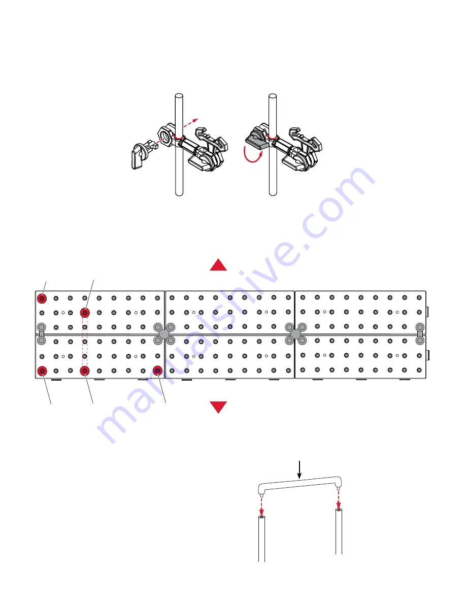
Insert 1 Shaft Connector into
the tops of the C and D shafts to lock
them in place.
Step 2
: Insert shafts A-E (bottom first) into the base assembly matching the shaft letter with the positions shown
below. Be sure to press shafts in firmly so they don’t rotate easily. Pay attention to back, front, up, down position
of arms as shown on diagram.
Arm attachment:
Rotate position of arm to match left, right, up, down orientation shown on diagram. Attach to shaft by slightly pulling
apart the open arm and inserting shaft. Then insert an Arm Lock and turn to lock in place as shown below. Note: if
you incorrectly used an Arm Holder A piece instead of an Arm Holder B piece, the shaft will not fit. See page 5 for the
difference and how to correctly assemble the arms.
Shaft Connector
D
C
C
D
E
B
A
Back
Front


