Introduction
3
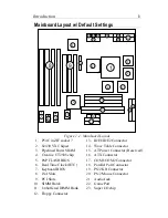
Mainboard Layout w/ Default Settings
6
1
16
2
2
8
9
2
3
3
2
4
5
7
23
13
12
11
10
15
14
21
21
22
21
18
19
20
17
Figure 1Ð1. Mainboard Layout
1. P54C in ZIF socket 7
13. IDE1/IDE2 Connector
2. 82430 VX Chipset
14. Wave Table Connector
3. Pipelined Burst SRAM
15. AT Power Connector (Reserved)
4. Creative CT2505 chip
16. ATX Connector
5. PnP FLASH BIOS
17. COM1/COM2 Connector
6. Real Time Clock (RTC)
18. Parallel Port Connector
7. Keyboard BIOS
19. PS/2 KB Connector
8. ISA Slots
20. PS/2 Mouse Connector
9. PCI Slots
21. Audio Jack
10. SIMM Bank
22. Game Port
11. Unbuffered DIMM Bank
23. Super I/O chip
12. Floppy Connector


