

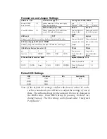
Connectors and Jumper Settings
CMOS clear: JP5
ATX Power Supply: P1
Cooling Fans: CPUFA, CHAFA
Retain CMOS
1-2
please insert the ATX power supply
pin
1
2
3
data (default)
plug into this header.
function
GND
12V
Sensor
Wake on LAN jumper: JP44
RESET
HD LED
Clear CMOS data
2-3
Please connect the WOL cable from
your LAN card to this jumper.
Connect the reset
button to this
jumper.
Connect the HDD
led to this jumper.
USB1 and 2
PRT
SPK
Keylock
Connect your USB devices to these headers
printer cable header
Connect the cable
Connect keyboard
ATX Power Supply On/Off Switch: PWRBT
of speakers to this
lock switch to this
Connect your power switch to this jumper (momentary switct type).
jumper
jumper
IrDA (Infrared Devices Connector: IR
TB Led
PW Led
pin
1
2
3
4
5
Connect your
Connect the
function
Vcc
FIRRX
IRRX
GND
IRTX
Turbo led to this
jumper.
power led to this
jumper.
PCI Audio Card Connection: SBLK1
Keyboard Wake Up: JP10
1
2
3
4
5
6
Wake Up Enabled
1-2
GNT#1
DGND
Empty
REQ#
DGND
SERIRQ
Wake Up Disabled
(default)
2-3
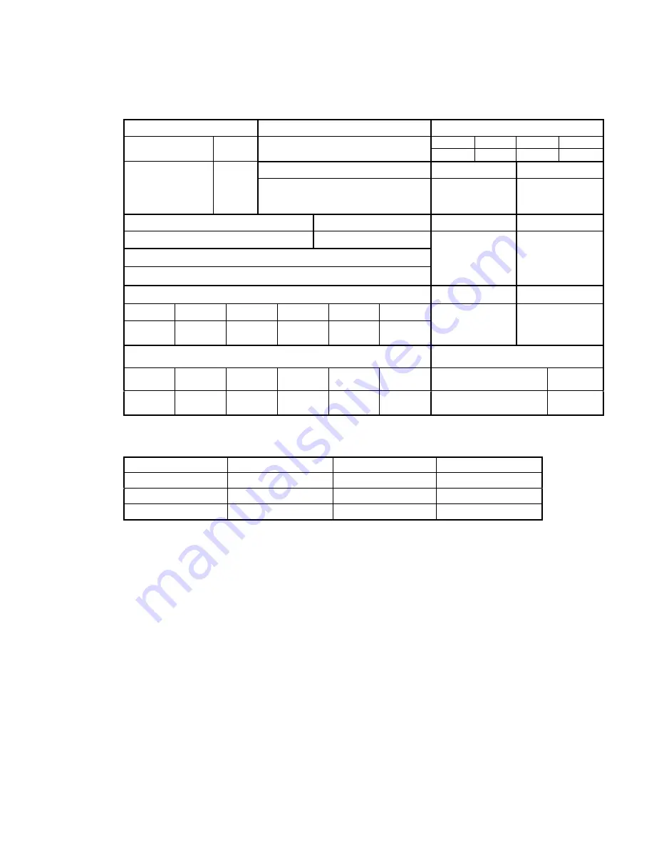
Default I/O Settings
PORT
I/O Address
IRQ
Functionality
LPT1
378H
7
SPP
COM1
3F8H
4
Ð
COM2
2F8H
3
Ð
Note: If the default I/O settings conflict with those of other I/O cards,
such as soundcards you will have to adjust the settings of one of
them. The default settings for the onboard I/O can be changed in
the BIOS setup. Enter BIOS Setup by pressing <Delete> key
during boot-up. The I/O settings can be found under ÒIntegrated
PeripheralsÓ.


