


8
Hardware Setup
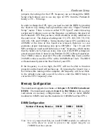
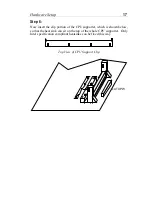
J25 – Front Panel Connectors
This set of connectors includes: Keylock/Power LED connector,
Speaker connector, Reset Connector, PWRBT, and Turbo/HDD LED
Connector. The features of each of these connectors are explained
below.
J25 Pin Assignment
Reset
Turbo
LED
HDD
LED
Keylock
Speaker
PWRBT
+
–
+
–
+
–
Power
LED
HD LED – IDE Device LED Connector
Attach a 2-pin IDE drive LED cable to this connector. The LED lights
when an IDE device is active.
TB LED – Turbo LED Connector
Attach a 2-pin turbo LED cable to it. The LED lights when the system is
in turbo mode. Manufacture default has set the board in turbo mode due
to most of hardware and software are compliance to turbo mode.
IDE LED – IDE HDD LED Connectors
Attach on-board IDE device LEDs to this connector. The LED lights
when an IDE device is active.
Keylock & Power LED Connector
This connector is for a lock that may be installed on the system case for
enabling or disabling the keyboard. This connector also attaches to the
caseÕs Power LED. (Pin 1, 3 for power LED, pin 4, 5 for keylock.)
SPK – Speaker Connector
Attach the system speaker to connector SPK.


