TRAK Machine Tools
Southwestern Industries, Inc.
The ProtoTRAK DXF Converter Operating Manual
15
is still active. Once you leave the event, you cannot undo the selections you made under
the event.
Event Data.
This button only appears in the last screen in the conversion process
(section 4.8). Clicking on the Event button will change the screen to show all the
prompts for the event. This is where you complete the programming of the event by
adding data like RPM, Feed Rate, Tool Number and other non-dimensional data not
available in the drawing. When you pick your event and geometry, click the Event key to
fill in the rest of the data needed.
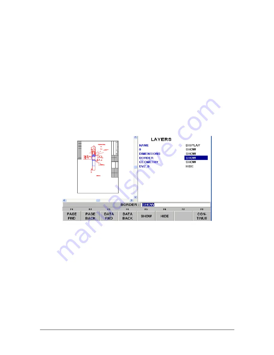
4.3 Choose the Layers That You Want Displayed
CAD files are made for printing, not machining. Therefore, DXF and DWG files usually contain
information that is good to have on a print, but not useful for machining. Examples include
borders, writing and dimension lines. To make the DXF conversion convenient, it is helpful to
eliminate those unneeded elements of the drawing from view.
The initial screen of the DXF
converter has all the drawing’s layers visible. This step allows you to
Hide unwanted information so you may focus on what you want to machine. See figures below.
FIGURE 4.3.1 The first screen you see when the DXF Converter launches. Notice that the entire
drawing, borders and dimensions, is shown on this first view


