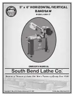
South bend SB1017 Owner'S Manual Download Page 4

INTRODUCTION

-2-

For Machines Mfg. Since 8/09

Model SB1017

I N T R O D U C T I O N

About This Machine

Capabilities

This metal cutting bandsaw uses a gravity-fed 

blade to make straight cuts through workpieces 

that are clamped in a vise. Since the workpiece is 

secured and remains stationary while the blade 

feeds automatically, accuracy and operator safety 

are maximized.

The vise on the Model SB1017 is capable of 

holding rectangular stock up to 5" x 6" and round 

stock up to 5". 

After a cut is complete, the OFF switch is 

triggered and the motor automatically turns off.

Features

In addition to its capabilities, the Model SB1017 

has several features to increase versatility and 

efficiency.

The vise can be rotated to perform angled cuts up 

to 45° while three blade speeds ensure that the 

proper cutting rate is available for a variety of 

workpiece sizes and materials.

Both the downfeed rate and pressure are 

adjustable for fine-tuning each cutting operation 

and an adjustable auto-OFF power switch 

maximizes safety and minimizes energy use by 

turning the machine off at the end of every cut.

A storage compartment in the cabinet base 

provides a convenient location for keeping spare 

blades or other accessories and the transport 

handle makes moving the machine easy. 

Finally, the cast-aluminum knobs and belt cover 

proudly bear the legendary South Bend name.

Summary of Contents for SB1017

Page 1: ...eds of Thousands of Lathes Sold With a Tradition of Quality Since 1906 Copyright May 2010 Revised February 2011 JB For Machines Mfg Since 8 09 MODEL SB1017 OWNER S MANUAL 5 x 6 HORIZONTAL VERTICAL BAN...

Page 2: ...s of operation is a process that happens through training and experience If you are not an experienced operator of this type of machinery read through this entire manual then learn more from an experi...

Page 3: ...es 48 Switch 50 Machine Labels 51 WARRANTY RETURNS 53 INTRODUCTION 2 About This Machine 2 Capabilities 2 Features 2 Identification 3 Machine Specifications 4 SAFETY 6 Understanding Risks of Machinery...

Page 4: ...addition to its capabilities the Model SB1017 has several features to increase versatility and efficiency The vise can be rotated to perform angled cuts up to 45 while three blade speeds ensure that...

Page 5: ...eased risk of seriously injuring themselves with this machine Do not operate this machine until you have understood this entire manual and received proper training Front View Rear View Blade Tension K...

Page 6: ...ght 47 lbs Length Width Height 17 x 13 x 23 Electrical Required Power Source 110V 220V Single Phase 60 Hz Switch Toggle ON OFF Switch Switch Voltage 110V Cord Length 6 ft Cord Gauge 18 gauge Recommend...

Page 7: ...ruction Cast Iron Base Construction Cast Iron Stand Construction Steel Tire Material Rubber and Steel Other Wheel Size 5 Blade Guides Upper Yes Blade Guides Lower Yes Table Info Floor to Cutting Area...

Page 8: ...ows Death or catastrophic harm WILL occur Moderate injury or fire MAY occur Death or catastrophic harm COULD occur Machine or property damage may occur Basic Machine Safety 1 Owner s Manual All machin...

Page 9: ...ng that all fastening devices are properly secured and items attached to spindles have enough clearance to safely rotate 11 Chuck Keys or Adjusting Tools Tools used to adjust spindles chucks or any mo...

Page 10: ...the teeth face toward the workpiece Wear gloves to protect hands and safety glasses to protect eyes 6 Workpiece Handling A shifting workpiece can result in impact or laceration injuries To reduce the...

Page 11: ...nd attached to the power supply Use a qualified electrician to ensure a safe power connection Before installing the machine consider the availability and proximity of the required power supply circuit...

Page 12: ...240V Cycle 60 Hz Phase Single Phase Circuit Rating 15 Amps Plug Receptacle NEMA 6 15 This machine can be converted to operate on a 220V power supply To do this follow the Voltage Conversion instructi...

Page 13: ...s or if you are in doubt about whether the tool is properly grounded If you ever notice that a cord or plug is damaged or worn disconnect it from power and immediately replace it with a new one Extens...

Page 14: ...ide Panel 1 Description Figure 4 Qty A Handle 1 B Axle 1 C Wheels 2 D Leveling Feet 2 E Handwheel 1 F Handwheel Handle 1 G Pulley Cover 1 H V Belt 1 Figure 4 Small components C D E B A F G H Hardware...

Page 15: ...de down on wood blocks to avoid scratching it or damaging the mounting tabs 3 Attach the handle to the left side panel as shown in Figure 8 with two M8 1 25 x 15 hex bolts and 8mm flat washers 4 Attac...

Page 16: ...own in Figure 12 You can adjust these later as needed to level the bandsaw 8 With the help of another person flip the stand assembly right side up then lift the bandsaw assembly and place it onto the...

Page 17: ...l the pulley cover Figure 16 with two M6 1 x 12 hex bolts three 6mm flat washers and the South Bend cast aluminum knob see Figure 17 13 Slide the vise handwheel onto the leadscrew and tighten the set...

Page 18: ...gh test them on an inconspicuous area of a painted area to make sure they will not damage it Basic steps for removing rust preventative 1 Put on safety glasses and disposable gloves 2 Coat all surface...

Page 19: ...e described in this manual Physical Environment The physical environment where your machine is operated is important for safe operation and longevity of parts For best results operate this machine in...

Page 20: ...is set up and adjusted properly 2 Clear away all tools and objects used during assembly and preparation Inspections Adjustments The following list of adjustments were performed at the factory before...

Page 21: ...wer the head and blade into the workpiece then allows the bandsaw to complete the cut 11 Once the bandsaw has stopped raises the head and removes the workpieces Loose hair clothing or jewelry could ge...

Page 22: ...the operator F ON OFF Toggle Switch Turns the saw motor ON or OFF G Vise Jaw Handwheel Controls the vise jaw movement H Downfeed Stop Bolt Adjusts to determine the absolute bottom limit of blade trave...

Page 23: ...idth Measured from the back of the blade to the tip of the blade tooth the widest point blade width is often the first consideration given to blade selection Blade width dictates the largest and small...

Page 24: ...tive rake angle and fast cut with good surface finish Skip or Skip Tooth Wide flat gullets a 0 rake angle equally spaced teeth and recommended for non ferrous materials Alternate An all purpose arrang...

Page 25: ...to the Material Width Diameter row of the blade selection chart in Figure 25 and read across to find the workpiece thickness you need to cut 3 Refer to the Material Shapes row and find the shape of t...

Page 26: ...ometimes possible to flip the blade inside out in which case the blade will be installed in the wrong direction Check to make sure the blade teeth are facing toward the workpiece as shown in Figure 27...

Page 27: ...blade tension Blade Tension Knob Blade Breakage Many conditions may cause a bandsaw blade to break Some of these conditions are unavoidable and are the natural result of the stresses to which bandsaw...

Page 28: ...orrect speed for the blade and material of the operation 2 Reduce the feed pressure by half for the first 50 100 in2 of material cut 3 To avoid twisting the blade when cutting wait until the total wid...

Page 29: ...k Silver or Light Brown Good Decrease Slightly Check Blade Pitch Hard Coiled Thin Silver Increase Decrease Check Blade Pitch Straight Thin Silver Good Increase Powdery Silver Decrease Increase Coiled...

Page 30: ...igure 36 then tighten the set screw to secure it The downfeed valve starts and stops headstock downfeed The downfeed rate is adjusted by turning the downfeed rate adjust knob Figure 35 Turning the kno...

Page 31: ...machinist square to set the angle of the vise fence as shown in Figure 38 The vise can hold material up to six inches wide and be set to cut angles from 0 to 45 Tools Needed Qty Wrench or Socket 12mm...

Page 32: ...crews removed in Step 2 6 Install the table bracket with the pre installed hex bolt the M6 1 x 12 flat head screw and the M6 1 hex nut as shown in Figure 43 Figure 43 Table installed Pre installed Hex...

Page 33: ...art a cut with the blade in contact with the workpiece Pay attention to the chips produced by the cutting operation and use their appearance to fine tune the blade speed feed speed and pressure refer...

Page 34: ...for the South Bend Lathe aficionado Figure 46 Antique finished South Bend shop clocks SB1298 SB1299 SB1300 Figure 47 Official South Bend Lathe T Shirts SBL Gearhead T Shirt SBL One Good Turn T Shirt 1...

Page 35: ...cation Before applying lubricant wipe the area clean for best results Lubricate the components shown in Figure 48 with multi purpose gear grease Gearbox At least once a year drain and replace the gear...

Page 36: ...o engine oil in place of the grease or rust preventative 3 Loosen or remove the belt so it does not become stretched during storage 4 Remove the four hex bolts that secure the gearbox cover then remov...

Page 37: ...to stop downfeed movement Proper placement of the downfeed stop bolt prevents the blade from contacting the machine base and the auto OFF tab from resting on the ON OFF toggle switch while still allo...

Page 38: ...adjusted to make square cuts One bearing on each assembly has an eccentric bushing that allows it to be adjusted to properly support the blade The bearings are secured in place by a hex nut and lock...

Page 39: ...ing the blade Hex Bolts The auto OFF tab may require adjustment over time if the machine fails to turn itself OFF at the end of a cut To adjust the auto OFF tab 1 DISCONNECT BANDSAW FROM POWER 2 Loose...

Page 40: ...Test for shorted windings bad bearings and repair or replace Machine has excessive vibration or noise 1 Blade is missing teeth 1 Replace blade 2 Motor fan rubbing on fan cover 2 Fix replace fan cover...

Page 41: ...decrease blade TPI 2 Blade guides need adjustment 2 Adjust blade guides 3 Blade is not tracking correctly 3 Adjust blade tracking 4 Blade is bell mouthed 4 Install new blade and regularly remove tens...

Page 42: ...h blade adjust feed rate adjust blade speed make sure the brush is working 4 The workpiece has hard spots welds or scale 4 Replace the blade with a special blade for cutting hardened materials Repetit...

Page 43: ...including serious injury or fire 4 Motor Wiring The motor wiring shown in these diagrams is current at the time of printing but it may not match your machine Always use the wiring diagram inside the...

Page 44: ...V 5 15 Plug As Recommended ON OFF Toggle Switch Ground MOTOR OVERLOAD 220V MOTOR OVERLOAD 110V 110V Wiring Loosen These Terminal Screws 3 Use a wire nut to connect wires 2 3 and 5 then wrap them with...

Page 45: ...tor 200MFD 125VAC 6 1 4 Start Capacitor 200MFD 125VAC ON OFF Toggle Switch 5 2 3 6 1 4 5 2 3 Ground Neutral Hot GND Ground 110 VAC Motor 110V Motor Rewired for 220V 5 15 Plug As Recommended MOTOR OVER...

Page 46: ...4 30 PEC03M E CLIP 10MM 156 PS06 PHLP HD SCR 10 24 X 3 8 31 PB03 HEX BOLT 5 16 18 X 1 157 PTLW01 EXT TOOTH WASHER 10 32 PSB1017032 VISE LEADSCREW W NUT 187 PW07 FLAT WASHER 5 16 32 1 PSB1017032 1 VISE...

Page 47: ...LT M8 1 25 X 15 4 3 PSB1017004 3 REAR TOP PANEL ASSEMBLY W DOOR 4 14 PW01M FLAT WASHER 8MM 4 4 PSB1017004 4 FRONT PANEL 9 PSB1017009 WHEEL ASSEMBLY 4 5 PB87M HEX BOLT M8 1 25 X 15 9 1 PSB1017009 1 WHE...

Page 48: ...19 46 47 54 208 207 61 17 43 50 212 51 120 50 71 1 198 113 51 412 80 103 1 214 109 103 4 103 5 72 100 120 123 2 103 2 103 3 81 90 75 104 189 93 92 3 118 59 2 59 59 1 59 3 55 3 55 1 55 55 2 3 55 4 71...

Page 49: ...8 55 PSB1017055 TABLE ASSEMBLY 103 PSB1017103 BLADE TENSION SLIDE ASSEMBLY 55 1 PSB1017055 1 FLAT HD SCR 1 4 20 X 1 2 103 1 PSB1017103 1 SHAFT BLOCK 55 2 PSB1017055 2 TABLE 103 2 PSB1017103 2 BLADE T...

Page 50: ...01 1 101 35 69 83 6 84 99 98 86 158 86 1 112 99 1 74 16 44 85 1 85 118 116 159 119 111 94 1 94 94 2 94 3 85 2 85 6 85 7 85 3 85 4 85 5 83 64 4 64 5 64 9 64 2 64 5 64 3 64 6 64 1 64 10 64 12 64 11 64 8...

Page 51: ...L SEAL TC 15 X 35 X 7 63 9 PSB1017063 9 DEFLECTOR PLATE 94 PSB1017094 WORM GEAR SHAFT ASSEMBLY 63 10 PFH19 FLAT HD SCR 1 4 20 X 3 8 94 1 PSB1017094 1 WORM GEAR SHAFT 63 11 PSB1017063 11 REAR BLADE GUI...

Page 52: ...017076 SWITCH SHUT OFF ASSEMBLY 203 2 PSB1017203 2 SWITCH COVER 76 1 PSB1017076 1 SWITCH SHUT OFF PLATE 203 3 PSB1017203 3 SWITCH INDICATOR PLATE 76 2 PW06 FLAT WASHER 1 4 203 4 PSB1017203 4 SWITCH HE...

Page 53: ...www southbendlathe com to order new labels 301 302 303 304 305 306 307 308 309 310 311 312 313 REF PART DESCRIPTION REF PART DESCRIPTION 301 PSB1017301 MACHINE ID LABEL 308 PSBLABEL01HS READ MANUAL LA...

Page 54: ...52 For Machines Mfg Since 8 09 Model SB1017 N O T E S...

Page 55: ...arrant or represent that this machine complies with the provisions of any law act code regulation or standard of any domestic or foreign government industry or authority In no event shall South Bend s...

Page 56: ...South Bend Lathe Co P O Box 2027 Bellingham WA 98227 PHONE 360 734 1540 Administrative Offices FAX 360 676 1075 International FAX 360 734 1639 USA only southbendlathe com Printed In Taiwan JB12681...

Reviews: