background image


7

(Only for SDR-342T) 


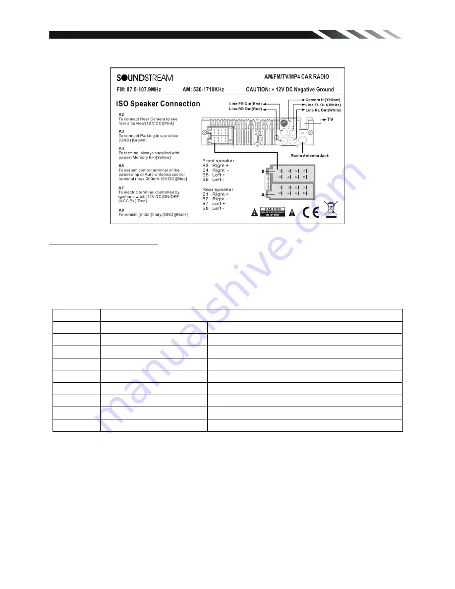
Using the ISO Connector 

1. If your car is equipped with the ISO connector, then connect the ISO connectors as illustrated. 
2. For connections without the ISO connectors, check the wiring in the vehicle carefully before 
connecting, incorrect connection may cause serious damage to this unit. 
3. Cut the connector; connect the colored leads of the power cord to the car battery as shown in 
the color code table below for speaker and power cable connections. 


Location Function 


Connector A


Connector B


1  

Rear 

Right(+)---Purple


2 Rear 

Camera---Yellow Rear 

Right(-)---Purple/Black Stripe


Parking (GND)---Brown


Front Right(+)---Grey


Battery 12V (+)---Yellow


Front Right(-)---Grey/Black Stripe


Auto Antenna---Blue


Front Left(+)---White


Front Left(-)---White/Black Stripe


ACC(+)---Red


Rear Left(+)---Green


Ground---Black


Rear Left(-)---Green/Black Stripe


Summary of Contents for SDR-342

Page 1: ...MP3 MP4 Player AM FM Radio Built in TV tuner only for SDR 342T model Owner s Manual Take the time to read through this owner s manual Familiarity with installation and operation procedures will help you obtain the best Performance from your new device ...

Page 2: ... weather wait until the temperature in the car becomes normal before operating the unit z DO NOT open covers and do not repair yourself Consult the dealer or an experienced technician for help z Make sure you disconnect the power supply and aerial if you will not use the system for a long period or during a thunderstorm z Make sure you disconnect the power supply if the system appears to be workin...

Page 3: ...Installation 5 Wiring Connections 6 Front panel 8 Inner panel 8 Remote control 9 Remove battery 9 Main Menu 10 General Operation 10 Radio operation 13 USB SD MMC Operation 14 TV Opeartion only for SDR 342T model 15 Anti theft system 16 Troubleshooting guide 17 Specification 18 ...

Page 4: ... 1 Washer Spring Washer M5 Nut 1 each 2 Mounting Strap 1 3 Bolt 5 20 1 4 Screw 5 6 4 5 Mounting Collar 1 6 Release Key 2 7 Screw 5 20 1 8 Rubber Cushion 1 Remote Control Warranty card ISO cable User Manual 1x front panel protection case Trim ring Noted Product image may vary from the actual delivery ...

Page 5: ...ounting tabs out with a screwdriver Make sure that lock lever is flush with the mounting collar not projecting outward 2 Secure the rear of the unit After fixing mounting bolt and power connector fix the rear of the unit to the car body by rubber cushion 3 Insert trim plate When you prepare to insert trim plate please check its direction Once it was up side down it cannot be fixed Un installation ...

Page 6: ...sing the ISO Connector 1 If your car is equipped with the ISO connector then connect the ISO connectors as illustrated 2 For connections without the ISO connectors check the wiring in the vehicle carefully before connecting incorrect connection may cause serious damage to this unit 3 Cut the connector connect the colored leads of the power cord to the car battery as shown in the color code table b...

Page 7: ...t 3 Cut the connector connect the colored leads of the power cord to the car battery as shown in the color code table below for speaker and power cable connections Location Function Connector A Connector B 1 Rear Right Purple 2 Rear Camera Yellow Rear Right Purple Black Stripe 3 Parking GND Brown Front Right Grey 4 Battery 12V Yellow Front Right Grey Black Stripe 5 Auto Antenna Blue Front Left Whi...

Page 8: ...10 Play Pause Memory button 11 Previous Reverse button 12 Next Forward button 13 IR sensor 14 LCD Screen 15 OPEN button 16 USB slot 17 AUX IN jack AV IN jack optional Inner panel 18 SD MMC card slot 19 Reset button 20 Anti Theft LED flash NOTE When turn off the power the unit will switch to standby mode unless cut the ACC power The power light will continue lighting ...

Page 9: ...for about one year although depending how often the remote control is used If the remote control unit isn t working even when it is operated near the unit replace the battery with a new battery of the same make and use only a lithium cell battery type CR2025 3V Dispose empty batteries in accordance with your local governmental regulations Do not short circuit disassemble heat or dispose of fire or...

Page 10: ...on the unit Long press POWER button on front panel or press power button on the RC to power off the unit Mode setting Press the MODE button repeatedly to switch between inputs RADIO USB SD TV AUX IN AV IN SETTING RADIO available only if there is media device in SD USB slot connection is OK Volume OK Adjust the volume level by turning the VOL knob on the panel clockwise to increase or counterclockw...

Page 11: ... battery power or resetting the unit all the settings will return to factory default settings Mute function Press POWER MUTE button on the panel or MUTE button on the RC to turn the sound off Press it again to resume the volume Loudness Long press EQ LOUD button on the RC or front panel to set loudness on or off EQ Press the EQ button on the panel to choose sound effect in the sequence of USER FLA...

Page 12: ...em information Product Info You can view detail system information including serial number of the software Default Set return to factory default setting or not AUX IN Connect an optional AUX cable to your external AUX device then press the MODE button to switch to the AUX mode AV IN OPTIONAL Connect an optional AV cable to your external AV device such as a video camera then press the MODE button t...

Page 13: ...press digital number 1 6 on the RC to select any present station Preset scan In tuner mode press the AS PS on the panel or RC to scan the preset memorized station each preset scan for 5 seconds Press again to stop operation Scan Press SCAN button on the front panel to search station it will playback 10 seconds when a station is found Press SCAN button again to confirm the station If you not confir...

Page 14: ...ause button Press number button 0 9 on the RC to select the desired track and then press ENTER button on the RC to confirm playback Random playback In Media file mode long press RDM button on the RC or BAND button on the front panel to set random playback on or off Fast backward forward During playback press and hold repeatedly SEEK or SEEK on the RC or the panel to activate fast backward or forwa...

Page 15: ...Stretch TV Opeartion only for SDR 342T model 1 Connect TV antenna and then press MODE button to select TV mode 2 In TV mode press the Play pause button once to enter TV menu setting 3 Press the buttons on the remote control or turning the knob clockwise or counterclockwise on front panel to select one of the setup pages Auto program Manual program 4 Press VOL button on front panel or ENTER button ...

Page 16: ... press icon to select channel z Fine Select this menu item is to fine TV tuning and sound until it achieves the best quality press button on remote to adjust z Memory Select memory on or off is to set whether memory the searched station or not press ENTER on remote control to select Anti theft system Remove the panel 1 Press the PWR button to turn the power off 2 Press OPEN button to detach the pa...

Page 17: ... properly connected Adjust volume to a desired level Check wiring connection The operation keys do not work The built in microcomputer is not operating properly due to noise Front panel is not properly fixed into its place Press the RESET button Reinstall the front panel The radio does not work the radio station automatic selection does not work The antenna cable is not connected the signals are t...

Page 18: ...Hz Frequency range EUROPE AREA 87 5 108MHz Step 50KHz Frequency range ASIA AREA 87 5 108MHz Step 100MHz Preset memory stations 18 AM MW Radio Frequency range U S A AREA 530kHz 1710 KHz Step 10KHz Frequency range EUROPE AREA 522kHz 1620 KHz Step 9KHz Frequency range AISA AREA 531kHz 1602 KHz Step 9KHz Preset memory stations 12 Audio specification Maximum output 2 Vrms 3 dB Frequency response 20 Hz ...

Reviews: