9
CN4...11
control output to electronic ballasts
1
DSI control
2
DSI control signal -
3
PE, GND
4
230V N
5
230V L
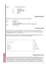
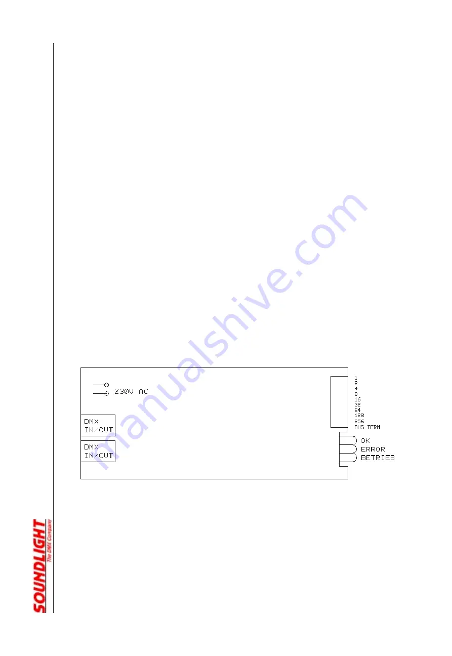
SIGNAL INDICATORS
Status signalling is with LED indicators:
green:
DMX data reception OK
red:
ERROR
normally off
blinks at transmission errors or at loss of signal
yellow:
power indicator
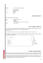
START ADDRESS SWITCHES
The coding switches set the start address, that is the address of the first channel to be decoded. Setting is in binary
format. To set an address, add the values of the appropriate switches, e.g.:
1+4+32+128 = 165
To set DMX channel 165 as the channel to control output #1, set switches "1", "4", "32" and "128"
Address 000 is not a valid address, minimum address setting is address #1. If address 0 has been selected, all outputs
are pulsed for service purposes.
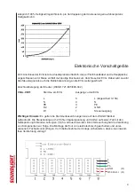
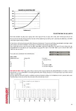
CONTROL CHARACTERISTIC
As the flourescent tubes are controlled fully digital, a precise control characteristic can be defined. Electronic control
is fully logarithmic, which produces a linear increase in intensity for the eye. This results in excellent intensity control
.
The tubes will ignite as soon as the DMX control signal reaches a value of 001 (equivalent to 1% intensity). A control
signal of 128 will result in 10% intensity, while a control value of 255 will result in 100% intensity. That is the logarithmic
law: doubling the input value will create a tenfold output value.


