background image

8

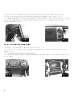
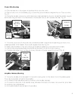
45. Remove the lower left nut securing the brake booster to the fi re wall. Fig. 24
46. Remove the screw securing the parking brake release handle. 
47. Slide the amplifi er bracket over the brake booster stud and then line up the hole in the front of the brack-
et with the hole in the parking brake release then reinstall the parking brake release screw. Fig. 25

Place your warranty card in the glove box for future use.

48. Reinstall the brake booster nut and tighten. Torque to 25Nm. Fig. 26
49. Remove the three screws securing the plastic panel below the steering column and then snap loose.
50. 

IMPORTANT: 

Ground the black ground wire of the amplifi er harness to the lower left bolt securing the 

metal knee bolster. Torque to 14Nm. Fig. 27

51. Install the white three pin connector on the end of the amplifi er power harness inside the cabin.  It does 
not matter what order the three wires are in on the three pin connecter but the terminals can only be inserted 
one way.  If the terminal will not go into the connecter simply turn it 180 degrees and try again.  Push the 
terminals in until they click and lock into place.  Install the black two pin connector on the end of the 
subwoofer power harness inside the cabin.  The black connector should have a block out plug installed in 
one side to prevent the power wire from being inserted into the wrong position in the connector.
52. Connect the white three-pin connector of the amplifi er harness to the corresponding connector of the 
amplifi er power harness.
53. Connect the black two-pin connecter to the power wire to the corresponding connector of the 
subwoofer harness.


Fig. 24 

Remove nut 

from this stud. 


Fig. 25 

Amplifier 

mounted over 

parking brake 

release lever.


Fig. 26 


Connect black 

ground wire 

here

Fig. 27 

Summary of Contents for PF150C13

Page 1: ...0 Super Crew vehicles 2012 Stillwater Designs PF150C13 A1 20121108 Subwoofer Assembly Subwoofer Power Harness Subwoofer Body Harness 25A Fuse Wire Ties x6 Foam Strips M6 Bolts x3 M6 Nut Inserts x3 Req...

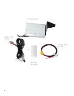
Page 2: ...2 Ampli er Assembly Ampli er Power Harness Ampli er Body Harness 25A Fuse Wire Ties x6...

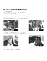
Page 3: ...n to park and turn ignition switch to off 6 Open the hood disconnect the negative battery cable 7 Remove the two screws on the top front of the console Fig 2 8 Remove the side panel of the console by...

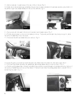
Page 4: ...to be loose enough to allow the left vent assembly to be removed 15 Pull loose the left vent assembly and remove Fig 8 16 Open the glove compartment and squeeze the sides inward to allow it to fold al...

Page 5: ...wiring 23 Remove the eight screws securing the display screen brack et and radio remove radio and disconnect wiring Fig 13 Radio Removal Trucks with Column Mounted Shifter 24 Remove the two screws in...

Page 6: ...sembly and remove the screw Place a towel under the airbag assembly to prevent it from scratching the dash Fig 17 Do Not Disconnect Any Airbag Wiring 30 Pull the left vent assembly loose and disconnec...

Page 7: ...both rubber grommets and pass the power wires into the cabin 39 Remove the driver s side threshold panel along the bottom of the front door opening 40 Pull back the rubber door molding and then pull b...

Page 8: ...on the end of the ampli er power harness inside the cabin It does not matter what order the three wires are in on the three pin connecter but the terminals can only be inserted one way If the termina...

Page 9: ...k the factory wires under the carpet out of the way 60 If the truck was not equipped with the factory subwoofer option measure ve inches from the sill plate under the rear seat and make an incision in...

Page 10: ...input signal connection to make sure it is secure and connected to the proper wiring Test with different music in case there is no low frequency audio in the initial sound check There is a buzz or rat...

Page 11: ...good ground Balance or fader controls not set to neutral position Set balance and fader control to center settings only effects stand alone subwoofer kit No low frequency information in music Test wi...

Page 12: ...12 P O Box 459 Stillwater Oklahoma 74076 USA 405 624 8510 stillwater designs...

Reviews: