background image

SoundField DSF-2


User Guide


Controls


Page 7


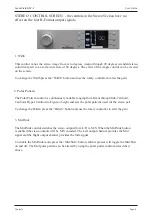
3. End  Fire


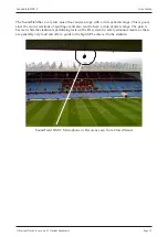
The End Fire mode should be selected when the microphone is horizontally pointed  ( 

) at the 

sound source as you would with a flashlight. Selecting End Fire maintains the correct three- 
dimensional perspective in both surround and stereo when the mic is used in the horizontal


position.


If you do not select this mode when the microphone is horizontal it will result in the Front/Back 
depth information and the Up/Down height information being reversed. This mode is particularly 
necessary when the microphone is mounted in a Rycote or on a fishpole and pointed directly at the 
sound source. 
 
To enable End Fire press the “End Fire” button - this will change the display to show the End Fire 
status in the middle of the screen – further presses of the “End Fire” button will toggle the status 
of End Fire on and off. 


To return back to the main screen either press the “End  Fire” button again or wait for the gain screen 
to automatically time out.


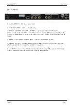
4. Invert


The INVERT mode maintains the correct three-dimensional perspective in both surround and 
stereo when the microphone is suspended upside down above the sound source   (   ).  Not 
selecting this mode with the mic suspended will result in the Left/Right width information and 
Up/Down height information being reversed. It is important to document the status of the Invert 
switch when making B-Format recordings for later post production.


To enable Invert press the “Invert” button - this will change the display to show the Invert status 
in the middle of the screen – further presses of the “Invert” button will toggle the status of  
Invert on and off. 
 
To return back to the main screen either press the “Invert” button again or wait for the gain screen to 
automatically time out.


5. High Pass Filter


The variable High-Pass filter – second order Butterworth – will filter the incoming microphone 
signals and will affect all output signals. Enabling the High-Pass filter is ideal for removing 
unwanted low frequency rumble such as wind noise, etc. 


To enable the High Pass Filter press the “High Pass Filter” button - this will change the display 
to show the High Pass Filter status in the middle of the screen – further presses of the “High 
Pass Filter” button will toggle the status of  Invert on and off and the rotary controller will alter 
the cut-off frequency. 
 
To return back to the main screen either press the “High Pass Filter” button again or wait for the 
gain screen to automatically time out.


Summary of Contents for DSF-2 MKII

Page 1: ...dcast Microphone System User Guide Version 1 0 System comprises DSF 2 MKII 1U Digital Microphone Controller DSF 2 Microphone in Leather Case 20m SoundField Microphone Cable Shockmount Mains Power Cabl...

Page 2: ...Started 4 5 Controls 6 9 Rycote Assembly Instructions 10 12 A Practical Guide For Use on 5 1 Outside Broadcasts 13 15 Interfacing the DSF 2 with the DSF 3 for Live Surround Broadcast 16 Specification...

Page 3: ...r the equipment Should this accidentally occur then immediately switch off the unit and contact your service agent Do not allow ventilation slots to be blocked Cleaning For cleaning the front panels o...

Page 4: ...onnector Push silver disc on microphone base at the red dot position to release connector When connecting the microphone cable to the DSF 2 controller ensure the red dot is facing upwards To disconnec...

Page 5: ...t to reverberant sound extraneous noises etc If it doesn t sound right move the microphone around until it does At this point adjust the Pattern control to focus more on the sound source and less on t...

Page 6: ...fixed threshold soft limiter is provided to eliminate the possibility of digital overload and any resulting distortion It is recommended that the limiter is engaged at all times particularly in wide d...

Page 7: ...de down above the sound source Not selecting this mode with the mic suspended will result in the Left Right width information and Up Down height information being reversed It is important to document...

Page 8: ...continuously variable ranging from Omni through Sub Cardioid Cardioid Hyper Cardioid to Figure of eight and sets the polar patterns used for the stereo pair To change the Pattern press the Pattern bu...

Page 9: ...al audio signals can be sent down up to one kilometer of coaxial cable subject to correct cable specification without loss of quality 3 WORD CLOCK INPUT AND OUTPUT 75Ohm wordclock I O on BNC 4 STEREO...

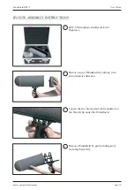
Page 10: ...INSTRUCTIONS 1 DSF 2 Microphone and Rycote kit in flightcase 2 Remove end of Windshield by turning in an anti clockwise direction 3 Loosen the two black plastic bolts situated on the Pistol Grip unde...

Page 11: ...POSITION IN THE STADIUM FOR END FIRE USE THE SOUNDFIELD LOGO ON THE MIC BODY MUST BE FACING DOWNWARDS SoundField logo facing downwards 7 When microphone is fully inserted tighten the two Allen bolts...

Page 12: ...the microphone cable into the groove provided on the underside of the Windshield before replacing end of Windshield Ensure the Windshield end is securely located in its original position 11 Insert Win...

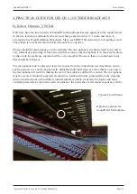
Page 13: ...ng It has been said that as long as the microphone is in the same stadium as the event the ambience captured will be very enjoyable However there are some basic rules that should be followed The micro...

Page 14: ...ndshield is then pointed at the main on field action In this position the microphone is said to be in End fire mode and the End fire switch on the Control Unit should be selected If the microphone is...

Page 15: ...ic range This is good since the crowd reactions of sporting events also tend to have a wide dynamic range The gain is best set while the stadium is performing tests on the PA system for safety announc...

Page 16: ...h not vital it is a big advantage to be able to monitor in full surround when choosing your mic position If monitoring in full surround is not possible during set up engaging the Rotate control at 180...

Page 17: ...psule Sensitivity 13mV Pa Signal to Noise Ratio DIN IEC 81dB Equivalent Noise DIN IEC 13dB Maximum SPL 145dB Word Clock I O Specification Word Clock input 75Ohm BNC 200mVpk pk minimum input level Word...

Page 18: ...ake such changes or improvements in the purchaser s unit Any dispute arising from this warranty shall be subject to the laws of England What to do if a fault is found or you need support In the unlike...

Page 19: ...n 5 RF Pin 5 Pin 6 RF Pin 6 Pin 7 LF Pin 7 Pin 8 LF Pin 8 Pin 9 Voltage GND Pin 9 Pin 10 V Pin 10 Pin 11 V Pin 11 Pin 12 Signal GND Pin 12 SOUNDFIELD COLOUR CODING Pin 1 White Pin 2 Purple Pin 3 Grey...

Reviews: