background image

Vi V4.5 Quickstart Guide.doc 

Page 8 


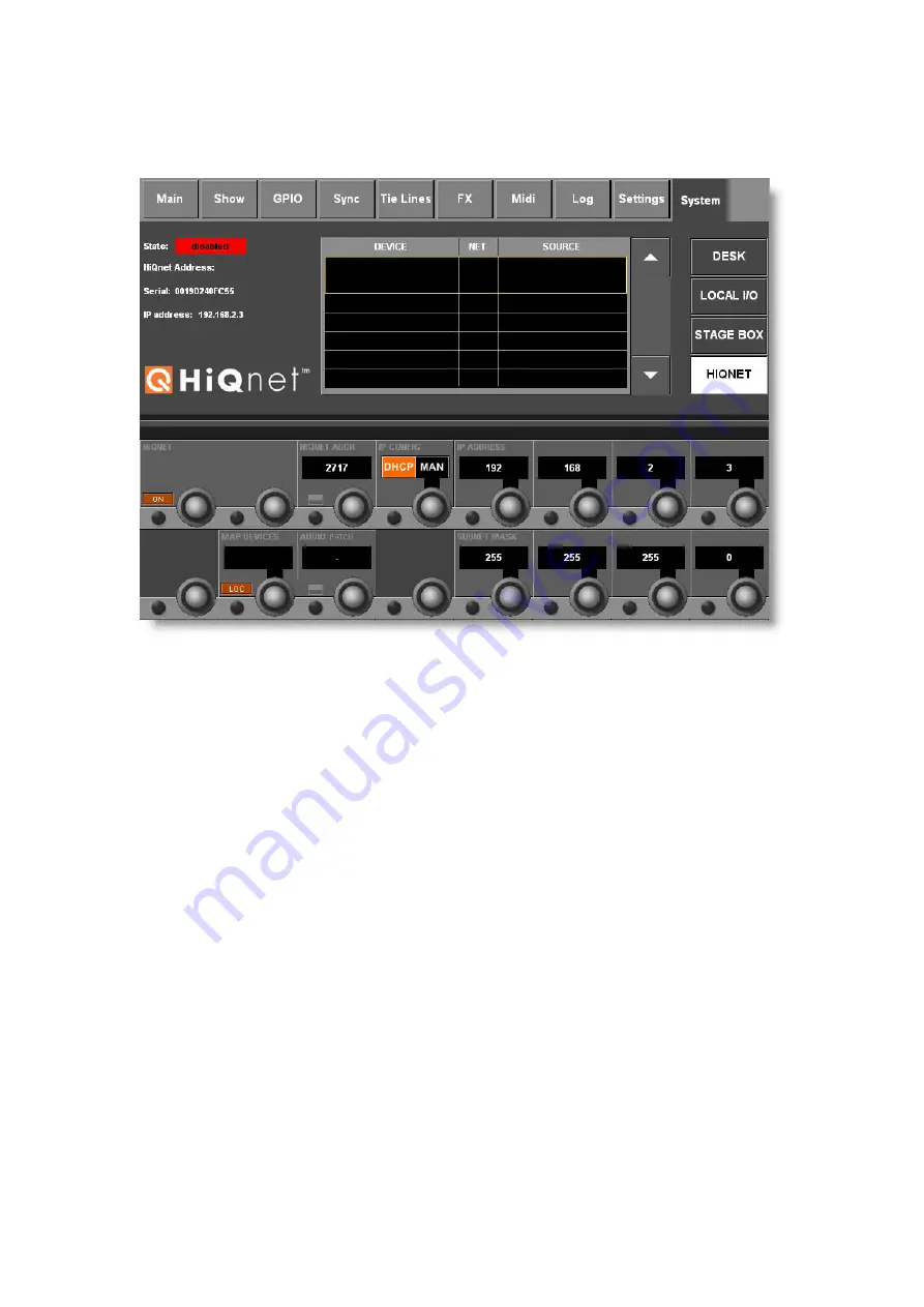
Using the Console’s HiQnet Setup page to set up an IP 

configuration 

 
Press the 

MENU

 button, select the 

System

 tab, then the 

HiQnet

 tab to access the 

Setup page. 
 

Configuring the IP Address  

Ensure the console’s HiQnet port is connected to the HiQnet network, and use the IP 
Config and IP address controls to set up a valid IP address for the console.  
If you wish to set the IP address and subnet manually, set the IP CONFIG Vistonics 
control to ‘MAN’. Use the IP ADDRESS and SUBNET MASK Vistonics controls to 
enter a valid configuration and then press the ‘SET’ button within the IP CONFIG 
control. 

 
The available ranges of valid IP addresses are listed below: 
Note: Some IP addresses within the ranges show are not allowed due to conflicts 
with other parts of the Vi system – they will be greyed out and not available for 
selection. 
 
10.0.0.0 - 10.255.255.255 
172.16.0.0 - 172.31.255.255 
192.168.0.0 - 192.168.255.255 

  
If you are using a DHCP server to automatically configure the IP setup, set the IP 
CONFIG Vistonics control to ‘DHCP’. Wait for several seconds until an IP address 
appears in the IP ADDRESS Vistonics control fields.  
When a valid address is established you will also see it on the far left of the HiQnet 
page. 
 
At this stage, all the controls in the HiQnet Vistonics section will be greyed out, 
indicating that HiQnet is disabled. 

Summary of Contents for Vi2

Page 1: ...V4 5 Software Quick Start Guide...

Page 2: ...Page 2 Contents Introduction to V4 5 VM2 3 VM2 Concepts 4 Setting up a VM2 Network 5 Identifying the HiQnet Network connector on Vi consoles 6 Detailed Console Operation of VM2 7 Using the Fader Calib...

Page 3: ...se also brings the operating software for all of the Vi consoles together into a single version which means that any type of Vi console can be updated from now onwards using a single update file downl...

Page 4: ...an devices to be displayed in the console s message log for example thermal overload messages generated by Crown amplifiers In addition the consoles were able to transmit a Venue Preset recall the HiQ...

Page 5: ...etwork Topology The example illustrated shows a typical setup with a front of house and Monitor console and a rack of AKG wireless receivers If only one console is being used and there is no other HiQ...

Page 6: ...ly Vi1 consoles serial numbers lower than 30210956 is only able to drive short cable lengths max recommended length 1 metre 3 feet Therefore use a network switch positioned close to the rear of the co...

Page 7: ...m the AKG Receivers to the console either to Stagebox or local inputs as appropriate Associate each AKG receiver with a console connector using the mapping table in the Vi s HiQnet Setup page The micr...

Page 8: ...ss the SET button within the IP CONFIG control The available ranges of valid IP addresses are listed below Note Some IP addresses within the ranges show are not allowed due to conflicts with other par...

Page 9: ...rk To set the HiQnet address press the button within the HiQnet Address Vistonics control see screenshot on previous page A keyboard will be opened which will allow the default address to be edited No...

Page 10: ...G Hub4000Q to which each microphone is connected In the example shown above there is only one Hub4000Q connected but it is possible for multiple Hub4000Qs to be connected to the network and in this ca...

Page 11: ...can still be chosen as an assignment for the currently selected microphone but a dialogue box will appear in this case to ask if you wish to reassign this connector Hint To avoid opening and closing...

Page 12: ...ing information will automatically be displayed in the channel strips where those audio patches are used The screenshot below has the first three channels with AKG mics assigned and shows the location...

Page 13: ...h of the battery within the AKG wireless transmitter The interior of the battery icon contains 7 segments showing varying battery level The colour coding of the battery icon is as follows Green Segmen...

Page 14: ...crophone Note that this information is display only there is no control possible over the AKG microphones other than the Locate button Note also that the input gain control of the Vi microphone input...

Page 15: ...System Architect must be used to discover what that is Once the address is known set the console to a different address but with the same subnet mask Problem No AKG receivers are detected by the conso...

Page 16: ...additive or auto cancelling Solo switches previously the Solo behaviour was fixed in AutoCancel mode When AutoCancel is switched off a specific channel can be left in Solo mode to act as a return talk...

Page 17: ...page if patched to BUS OUT Pan controls in Lexicon Delay FX worked in reverse OSC to BUS could not be routed to matrix busses Only first 8chs of User Layers appear if Vi6 show loaded on Vi1 Horizonta...

Page 18: ...n Vi1 whilst changing output fader pages Instructions for Recalibrating the faders 1 Navigate to MENU System Desk and press the FADER CAL button on the right hand side of the touchscreen Answer YES to...

Reviews: