


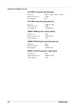
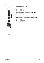


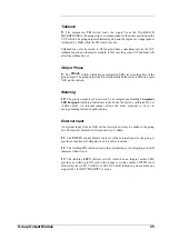


Insert Point
The module insert point uses a groundcompensated send and an electronically
balanced return, at a nominal level of -2dBu. The signal is accessible via separate
1/4" jacks on the rear connector panel.
The insert point may be set to pre- or post-EQ by pushon jumpers. The factory
default is post-EQ.
Output
13
The
electronically
latching
PFL switch feeds the pre-fade, pre-mute signal to
the PFL bus, which in turn feeds the engineer’s wedge speakers and phones outputs
via the Master section. An integral amber LED indicates when the PFL switch is
active.
14
The signal in the module is turned on and off by the CUT switch and by the
mute buses (see next paragraph).
An integral red LED in the CUT switch indicates when the signal is cut.
15
Each Input module is assigned to the four mute buses via the M1 - M4 buttons.
Each switch has an integral red LED, which indicates when the module is assigned
to its respective mute bus.
When the module is muted by any of the mute buses, the LED in the CUT switch
illuminates.
16
The Post-fader signal level is controlled by a 60mm Fader. The post-fader
signal is routed to the Direct Out jack on the rear connector panel: this is a ground
compensated output at a nominal level of -2dBu.
The post-fader signal is also fed to the Groups and the Stereo Mix buses (see below).
Groups
17
The input signal is sent to the group 1 - 16 buses via individual Level Controls.
These have unity gain when fully clockwise, and are activated using the associated
ON switches. Each switch has an integral green LED.
18
The group sends are switched pre- or post-fader by the PRE buttons. The
pre-fade signal may be sourced from one of the following three options:
•
post-mute and pre-fade
•
pre-mute
•
pre-EQ and pre-insert.
The source selection is done in two blocks of eight sends, using push-on jumpers.
The factory default is post-mute and pre-fade.
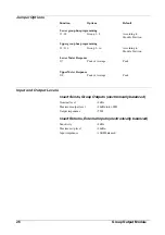
1
2
14
13
5
6
15
19
7
9
11
12
17
3
4
8
10
16
20
18
18
Input Module
Summary of Contents for SM 16
Page 1: ...SOUNDCRAFT USER GUIDE 16 ...
Page 5: ...Introduction Introduction 1 ...
Page 10: ...6 Introduction ...
Page 11: ...Installation Installation 7 ...
Page 14: ...10 Installation ...
Page 15: ...Module Block Diagrams Module Block Diagrams 11 ...
Page 16: ...PFL BUS GROUPS 1 16 BUSSES R STEREO BUS L STEREO BUS Input Module 12 Module Block Diagrams ...
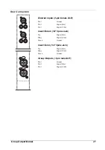
Page 17: ...Group Output Module Module Block Diagrams 13 ...
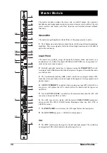
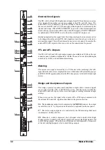
Page 18: ...Master Module 14 Module Block Diagrams ...
Page 19: ...Input Module Input Module 15 ...
Page 26: ...22 Input Module ...
Page 27: ...Group Output Module Group Output Module 23 ...
Page 32: ...28 Group Output Module ...
Page 33: ...Master Module Master Module 29 ...
Page 41: ...Appendices Appendices 37 ...


