


,QVWDOODWLRQ
The SM16 is designed for reliability and high performance, and is built to the highest
standards. Whilst great care has been taken to ensure that installations are made as
troublefree as possible, care taken at this stage, followed by correct setting up will
be rewarded by a long life and reliable operation.
Wiring Considerations
A For optimum performance it is essential for the earthing system to be clean and
noisefree, as all signals are referenced to this earth. A central point should be
decided on for the main earth point, and all earths should be ’star-fed’ from this
point. It is recommended that an individual earth wire be run from each electrical
outlet, back to the system star point to provide a safety earth reference for each piece
of equipment.
B Install separate mains outlets for the audio equipment, and feed these
independently from any other equipment.
C Avoid locating mains distribution boxes near audio equipment, especially tape
recorders, which are very sensitive to electromagnetic fields.
D Where possible ensure that all audio cable screens and signal earths are
connected to ground only at their source.
Power Supply (CPS900)
Always ensure that you use the correct PSU for your mixer. The SM16 uses a
CPS900 power supply.
Warning!
Before switching on your SM16 console, check that the mains
voltage selectors on the power supply unit is set to the correct
mains voltage for your area, and that the fuse is of the correct rating
and type. This is clearly marked on the case of the power supply.
Do not replace the fuse with any other type, as this could become a
safety hazard and will void the warranty.
8
Installation
Summary of Contents for SM 16
Page 1: ...SOUNDCRAFT USER GUIDE 16 ...
Page 5: ...Introduction Introduction 1 ...
Page 10: ...6 Introduction ...
Page 11: ...Installation Installation 7 ...
Page 14: ...10 Installation ...
Page 15: ...Module Block Diagrams Module Block Diagrams 11 ...
Page 16: ...PFL BUS GROUPS 1 16 BUSSES R STEREO BUS L STEREO BUS Input Module 12 Module Block Diagrams ...
Page 17: ...Group Output Module Module Block Diagrams 13 ...
Page 18: ...Master Module 14 Module Block Diagrams ...
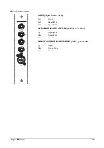
Page 19: ...Input Module Input Module 15 ...
Page 26: ...22 Input Module ...
Page 27: ...Group Output Module Group Output Module 23 ...
Page 32: ...28 Group Output Module ...
Page 33: ...Master Module Master Module 29 ...
Page 41: ...Appendices Appendices 37 ...


