www.soundskulptor.com
Document revision 2.1 – Last modification : 11/09/20
MP 512 Main board Assembly guide
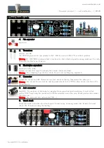
14. Small electrolytic capacitors
Add C4, C6, C7, C20, C21.
Solder one lead first, adjust verticality then solder the second lead.
Warning
: The +lead must go into the +hole. Do not reverse (they may explode !)
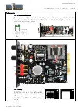
15. Switches
Add SW1, SW2 and SW3. The position of the switches is critical for a good front-plate matching. They
must sit flat on the PCB. Press firmly the switch on the PCB and solder one of the front pins (housing).
Check verticality and horizontality. Then solder the other pins.
16. Potentiometers P1 & P2
Place the bracket on the potentiometer bushing, and attach it with the lock washer and nut. Tighten.
Insert potentiometer and bracket into the PCB holes. Solder the central potentiometer pin. Now check
that the potentiometer shaft is perfectly parallel to the board. Then solder the other pins.
Warning
: A good potentiometer position is very important for a good match with the front panel.
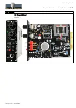
17. Input transformer
Pin 1 on the transformer is identified by a red dot. Insert the transformer, pin 1 into hole number 1.
Leave a small gap under the transformer in order that the case doesn't touch the PCB pads.
Start soldering 2 opposite pins, check the position, adjust if necessary then solder the other pins.
Warning
: Double check the pin 1 position because this transformer can be mounted backwards!
Copyright ©2013 SoundSkulptor


