www.soundskulptor.com
Document revision 2.1 – Last modification : 11/09/20
MP 512 Main board Assembly guide
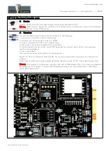
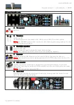
5. Led
Bend the leads of D7
right angle at 6mm from
the body taking care of
the anode position (the
longest lead).Insert from
the PCB bottom and
solder with the LED body lined up with the PCB surface.
Warning
: it is easy to bend the leads in the wrong direction !
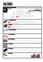
6. Integrated Circuit
Insert U2 and solder. You will need to bend the pins slightly inwards before inserting.
Warning
: Make sure to respect the IC direction, marked by a notch. Do not use a socket because it
would be to high for the DI board.
7. Relays
Add RLY1 & RLY2. Eight pins only are soldered.
Warning
: Make sure to respect the direction of the relays which is marked by a white line on the relay
and on the PCB marking.
8. Ceramic capacitors
Add C1, C2, C3, C5, C8, C17, C18, C19.
9. Film capacitors
Add C10
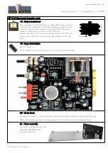
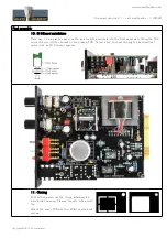
10. Jumper header
Solder the jumper header JMP1. Solder one pin first, check verticality, then solder the other pin.
11. Test pins
Solder the 6 test pins TP1, TP2, TP4, V+, V- and 0V.
12. Connector
Solder the connector socket CN1. Solder one pin first, check verticality, then solder the other pins.
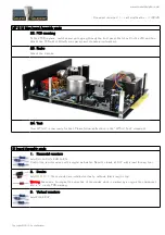
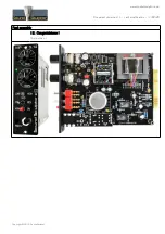
13. Inductor
Add L1. This inductor is installed vertically.
Copyright ©2013 SoundSkulptor


