background image

RackPack: Preference Mic Pre

17

Block Diagram

Summary of Contents for Preference Mic Pre 2711

Page 1: ...Manual PreferenceMicPre Single channel microphone preamplifier module RackPack Module Model 2711 11 76 7 1 20 SIG OVL 10 7 5 3 1 0 3 5 0 30 50 70 1 00 50 70 1 00 VU E 1 3 3 13 ...

Page 2: ...of Equipment Audio Signal Processor Product RackPack Preference Mic Pre Model 2711 Compliance Engineer Wolfgang Neumann Test Basis EN50081 1 1992 EN50082 1 1992 EN60065 1993 EN61000 3 3 1995 EN60065 2002 EN55013 2001 EN55020 2002 EN61000 3 2 2000 73 23 EWG 93 68 EWG We herewith declare that the construction of the Preference Mic Pre Model 2711 is in compliance with the standards and regula tions m...

Page 3: ...Control Elements 10 MicGain About Leveling 10 VU Meter PPM 10dB 11 48 V Phantom Power Supply Pad 12 Phase Reverse High Pass Filter Signal LED Overload LED 13 Technology 14 SSM 2019 Servo Drive Design 14 Foil And Styroflex Capacitors Outputs Channel Split 15 Copy Master Recall Settings 16 Block Diagram 17 Specifications 18 Measurements 19 CMRR Frequency Range 19 Guarantee 20 Contents ...

Page 4: ...d out by qualified persons In the light of possible physical damage or injuries any manipulation is at your own risk In order to avoid any residual voltage the device should be disconnected from any power source at least 5 minutes prior to opening it If you handle the device improperly or ignore the manual part of the delivery of the RackPack frame you risk to damage the device or expose yourself ...

Page 5: ...achine and immediately contact a qualified technician when you think repairs are needed or when moisture or foreign objects may accidentally have gotten in to the housing or in cases when the machine may have fallen and shows any sign of having been damaged This also applies to any situation in which the machine has not been subjected to any of these unusual circumstances but still is not function...

Page 6: ...XCLAMATION MARK WITHIN A TRIANGLE IS INTENDED TO MAKE YOU AWARE OF IMPORTANT OPERATIONAL ADVICE AND OR WARNINGS THAT MUST BE FOLLOWED BE ESPECIALLY ATTENTIVE TO THESE AND ALWAYS FOLLOW THE ADVICE THEY GIVE The symbol of a lamp directs your attention to explanations of impor tant functions or applications Attention Do not attempt any alterations to this machine without the approval or supervision o...

Page 7: ...ound The section Technology from page 14 explains how the Preference Mic Pre meets these requirements Main Features The Preference Mic Pre offers preamplification values of up to 72dB with lowest noise operation and a high common mode rejection A VU meter with two modes for average levels VU and peak levels PPM displays the output levels A very stable phantom power supply 48V is provided to power ...

Page 8: ...8 RackPack PreferenceMicPre Rear Panel Connections Wiring JDSPQIPOF JDSPQIPOF 0 POJUPSJOH 8 456 0 7 VF JY POJUPSJOH VSUIFS PEVMF 0 6 5 1 6 5 065 1 6 5 0 6 5 1 6 5 065 1 6 5 1 6 5 1 6 5 3BDL1BDL PS ...

Page 9: ... independent outputs it always offers you two routes for one input channel If for example a RackPack is configured as a channel strip one pre amp output can feed the next module while the second output is used to record the direct preamp signal Another exemplary studio application is to send one signal directly into the A D converter to be recorded in your DAW while the second signal is used for l...

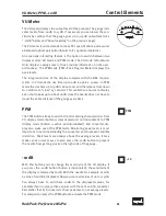
Page 10: ...he VU meter displays max imum levels between 0dB and 3dB At this level you don t risk any overdrive when you experience sudden and unexpected peaks in the level of the source Always remember that the VU meter only shows average values and that a peak level can be much higher up to 10dB If necessary turn on the PPM mode to see the actual peak levels Usually levels of around 0dB and 3dB are safe If ...

Page 11: ...not have to travel the entire distance of the gauge every time PPM The PPM button allows to switch the VU metering characteristics from VU display mode button is deactivated and not illuminated to PPM display mode button is active and illuminated A D converter dis play also make use of the PPM mode Monitoring peak levels is most important to avoid overloading the converter and to prevent audible d...

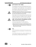
Page 12: ...hones including tube microphones which are supplied from their own power supply thus need no extra phantom power supply ALWAYS FOLLOW THESE RULES WHEN WORKING WITH PHANTOM POWER THE INPUT STAGES OF THE PREMIUM MIC PRE CAN BE DAMAGED IF YOU DO NOT ACT ACCORDINGLY 1 First connect the microphone to the Preference Mic Pre 2 Then activate phantom power you can start working now 3 When you have finished...

Page 13: ... in the mix High Pass Filter The high pass filter also known as rumble filter helps to eliminate any interferences within the lowest frequencies The first order filter operates smoothly with 6dB per octave starting from 75Hz with 3dB This characteristic usually helps in most cases and has the least sonic disadvantages If you need to filter on a more extreme scale even second order filters 12dB oct...

Page 14: ...ially when amplifying a microphone signal because the signal is amplified by extreme factors from the pico volt range to 0dB nominal level DC off sets impair the signal quality as they induce noise and distortion that lead to a diffuse sound The Preference Mic Pre s servo drive design minimizes these problems much more effectively than the common solution based on capacitors by setting the DC offs...

Page 15: ...es and the input stages on the other end The maximum output level is 22 dBu Channel Split Since the Preference Mic Pre has two independent outputs it always offers you two routes for one input channel If for example a RackPack is configured as a channel strip one output can feed the next module while the second output is used to record the direct preamp signal Another exemplary studio application ...

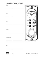
Page 16: ...16 RackPack PreferenceMicPre Copy Master Recall Settings Artist Album Title Engineer Track s Group Date 11 76 7 1 20 SIG OVL 1 0 7 5 3 1 0 3 5 0 30 50 70 100 50 70 1 00 VU E 1 3 3 13 ...

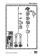
Page 17: ...RackPack PreferenceMicPre 17 Block Diagram ...

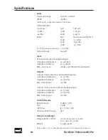
Page 18: ...edance balanced ca 3 2kOhm Max Input Level 18dBu 38dBu with Pad activated Outputs Output 1 XLR connector electronically balanced Impedance unbalanced ca 75Ohm Impedance balanced ca 150Ohm Max Outpul Level 22dBu Output 2 XLR connector electronically balanced Impedance unbalanced ca 75Ohm Impedance balanced ca 150Ohm Max Outpul Level 22dBu Control Elements MicGain Range 18dB to 72dB Pad 20dB High Pa...

Page 19: ... 2 100 50 90 80 70 60 d B u 10 20k 20 50 100 200 500 1k 2k 5k 10k Hz Sound Performance Lab 08 20 07 12 13 27 Frequency Response THD N ratio Freq Resp THD at27 Frequency Response and THD N ratio with 30dBu input level and vu 30dB black frequency response grey THD N ratio 0 025 0 2 0 05 0 075 0 1 0 125 0 15 0 175 3 3 2 1 0 1 2 d B u 10 200k 20 50 100 200 500 1k 2k 5k 10k 20k 50k Hz ...

Page 20: ...guarantee through their distribu tor or dealer In such cases please contact your dealer for full guaran tee conditions and service Direct SPL product support requires product registration Please fill out the guarantee card enclosed in the package legibly in printed let ters and send it directly to SPL Or use the online registration form that may be reached at www soundperformancelab com internatio...

Reviews: