


- Page 3 -
3.3
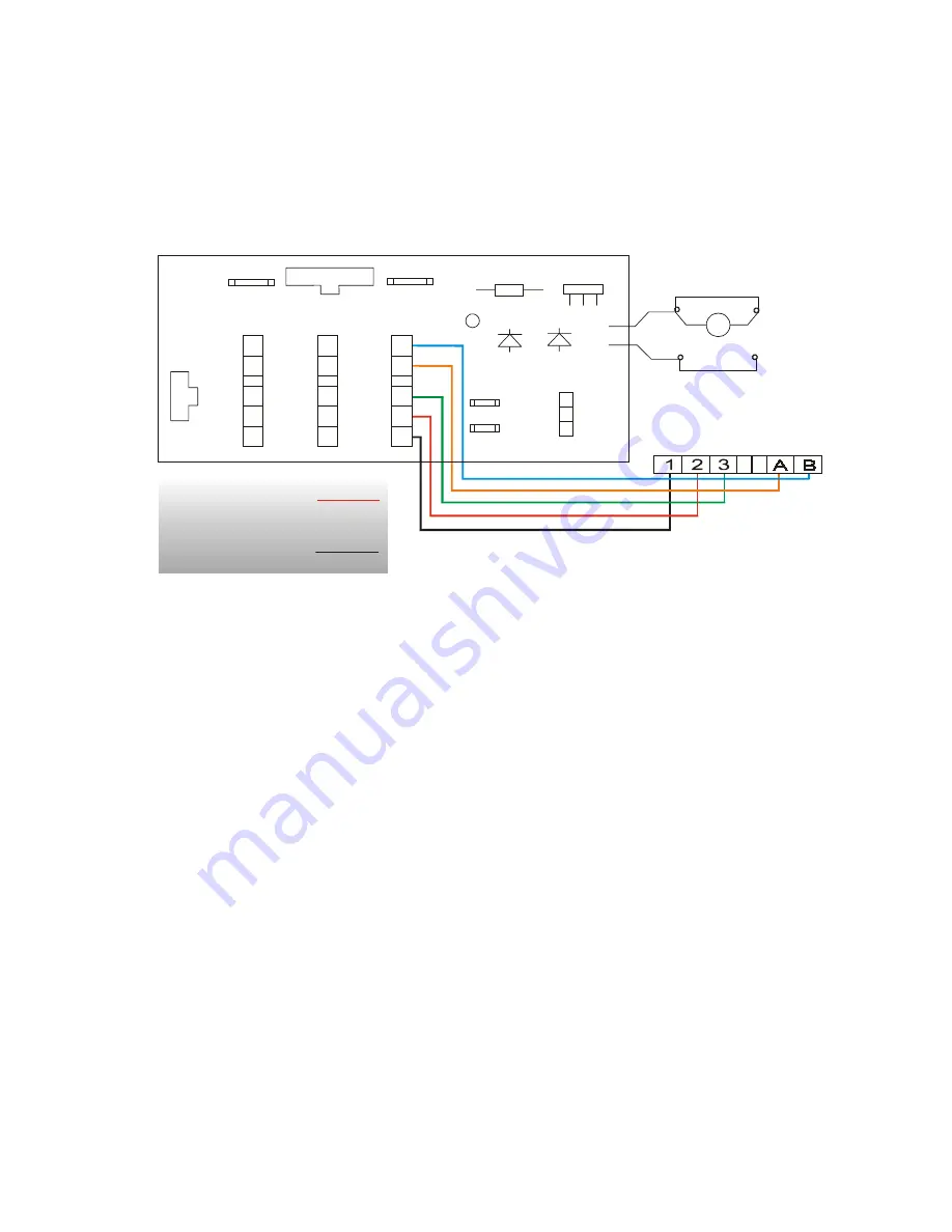
SYSTEM CONNECTION
There are three wallbox connectors in the jukebox/hideaway system each having
five terminals. These are located on a small circuit board labelled: 'Wall Box
Distribution Board' as shown below.
A
B
3
2
1
A
B
3
2
1
WALLBOX DISTRIBUTION BOARD
2A
2A
2A
MPU
Wb1
Wb2
Wb3
A
B
3
2
1
C2
R1
VR1
D1
D2
3.15A
3.15A
14V
14V
0V
+5V
0V
PAGE
MOTOR
PAGE Sw1
PAGE Sw2
Page motor wiring for
units without a
SLE 101A Board fitted
Power line cables on
Terminals 1+3
Signal cables on
Terminals A and B
Each wallbox should be individually wired back to the jukebox/hideaway
unit.
3.4
CABLE REQUIREMENTS
The connection between individual wallboxes and a jukebox/hideaway
unit is done via five cables as shown above.
Connectors are located within each piece of equipment. These
connectors have terminals labelled 1, 2, 3, A and B.
Connect 1 to 1, 2 to 2, 3 to 3, A to A and B to B.
Cables connected to terminals 1 and 3 must have a minimum conductor
diameter of 1mm (0.75mm² cross sectional area) when connecting wallboxes up
to 50meters away and 1.5mm diameter (1.5mm² cross sectional area) when the
wallbox is up to 100meters away.
Terminals 1 and 3 handle the wallbox low voltage supply. The power is supplied
by the hideaway/jukebox as 14-0-14V a.c.
Terminal 2 is the common ground return.
Summary of Contents for Mini Jook
Page 4: ......


