Page 2
FM1
F
AST
M
OUNT
33-4210 05/06
GENERAL NOTES
Please read these instructions and guidelines entirely before
installation.
Always consult with Local Authorities in order to obtain specifi c
requirements of an installation or product utilization.
Make sure wiring, termination and securing procedures comply
with the National Electrical Code (NEC) , NFPA 70 and any other
Local Electrical and Building Codes.
It is always recommended to support the system from a struc-
tural point of the building, even if not required by Local Codes.
The FM1 Series Loudspeaker is fi tted with a seismic tab that
enables conveniently connecting the speaker to the building
structure (see
Figure 8
).
If local codes require the use of conduit, ensure that it is well
supported. Too much unsupported weight may prevent the
loudspeaker from closing fl ush against the ceiling surface. For
convenience, the FM1 is suplied with a clamp-style strain-relief
fi tting installed on the rear cover.
CONTENTS
The shipping carton contains two (2) FM1 Integrated Loudspeak-
ers, mounting hardware and Installation Instructions. Two (2)
cutout templates can be found on the shipping carton.
NOTE: Orders placed for Existing Construction include a
TBS-FM1 Support Bridge with every loudspeaker, and it is
shipped on the same shipping carton.
Orders placed for New Construction installation include a
NCB-FM1 New Construction Bracket with every loudspeaker,
shipped separately to facilitate pre-installation before the
ceiling is fi nished. (See
Figure 2
.)
UNPACKING AND INSPECTION
Open the shipping cartons carefully and remove all contents.
Inspect the product and accessories for damage. Report damage
or shortages to Sound Advance immediately.
CAUTION: The FM1 uses a fl at polystyrene material as the
sound-radiating surface. Although it is resistant to mechanical
damage and is unaffected by environmental extremes, care
should be observed during handling, to avoid punctures or
other damage.
INSTALLING THE MOUNTING HARDWARE
TBS-FM1 SUPPORT BRIDGE INSTALLATION IN
EXISTING CONSTRUCTION
The FM1 can be installed in a wide range of ceiling materials, from
3/8 inch up to 1¼ inches thick. The TBS-FM1 Support Bridge is
23¾ inches (603 mm) long and will support the loudspeaker in
a 2 ft. by 4 ft. (or 2 ft. by 2 ft.) ceiling tile. If angled at 10 to 15
degrees, the TBS-FM1 can also be used with 600mm tiles.
1.
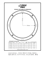
Remove the cutout template from the shipping carton and
temporarily attach it to the ceiling in the desired location.
2. Check for electrical conduit and other obstructions behind
the ceiling in the mounting area before cutting the hole. In
addition, allow suffi cient clearance for both the depth of
the loudspeaker/enclosure and any electrical fi ttings (8¾”
minimum).
3. Cut the hole for the speaker.
• The mounting hole for the speaker is 10¾ in. (273mm)
in diameter.
4.
Engage the loose end of the springs into the “install” tabs
in the TBS-FM1 Support Bridge (see
Figure 3
).
TBS-FM1 Bracket
(x2, Included with speakers)
NCB-FM1 Bracket
(x2, Shipped separately)
FM1 Speaker (x2)
Install Tab
(with Spring Engaged)
Figure 2: FM1 Carton Contents
Figure 3: Engaging the Springs in the Install Tabs


