20 von 36
Service record Dynamis MV
Service record Dynamis MV
2021-01-12
3.6
Brakes assembly
3.6.1 General information about the brake
(1)
(A)
(D)
(C)
(B)
(2)
(C)
Technische Angaben beachten
!
(2)
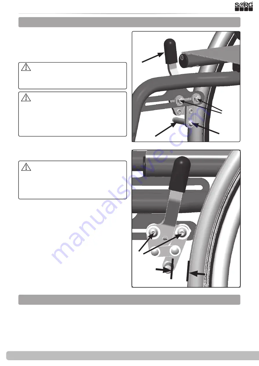
First check the tire pressure of the drive wheels (required information on the tire casing). To
adjust the brake, loosen the two screws
(C)
on both sides, bring the brake body into the corres-
ponding position and tighten the screws
(C)
again.
3.6.2 Standard parking brake
max.
21 mm
Parking brakes are used only to lock the
wheels in a rest position. They are
not
de-
signed to brake the wheelchair while it is in
motion.
The correct functioning of the brakes
can be impaired by:
• tire pressure too low,
• Wetness, dirt, snow, ice, etc..
•
worn tire profile and
• Too great a distance between the brake
pressure bolt and the tire.
Check the fastening of the brake pressure
bolts on the inside of the wheelchair at regular
intervals
(D)
Readjust the brakes after making any
changes to the drive wheels. On a ramp with
a 12.3% (7 °) gradient, the wheelchair's drive
wheels with occupants must not slip when
the parking brake is on.
(1+2)
Every wheelchair is equipped with two
parking brakes or knee lever brakes. They con-
sist of brake pressure bolts
(A)
, brake lever
(B)
(if necessary with an extension) and adjusting
screws
(C)
.
When the brake is open, the maximum dis-
tance between the brake pressure pin and the
tires is set as follows:
Standard-KLB
21 mm
Pull-to-lock-brake
11 mm
KLB with anti-rollback
about 10 mm
Bowden cable brake
6 mm
(Technical changes reserved).


