background image

26

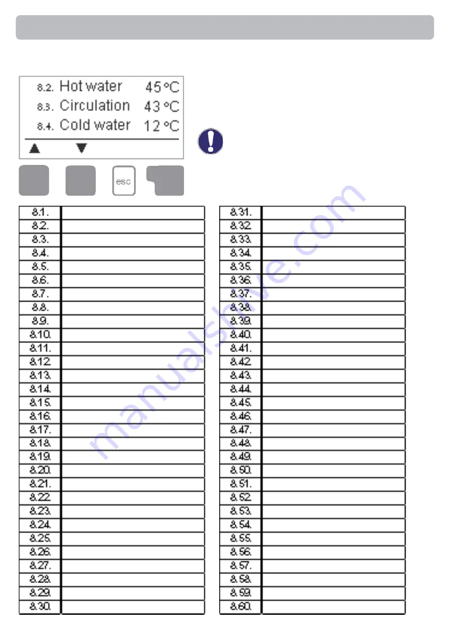
The menu “8. Service values” can be used for remote 
diagnosis by a specialist or the manufacturer in the 
event of an error, etc.

Caution

Enter the values at the time when the error 
occurs e.g. in the table.

The menu can be closed at any time by pressing “esc”.

Service values

8. - Service values

Summary of Contents for FWC3

Page 1: ...Fresh Water Controller FWC3 Installation and operating instructions Read carefully before installation commissioning and operation...

Page 2: ...s 16 2 1 Operating hours HW 16 2 2 Operating hours circ 16 2 3 Heat output 16 2 4 Graphic overview 16 2 5 Error messages 16 2 6 Reset clear 16 3 Display mode 17 3 1 Schematic 17 3 2 Overview 17 3 3 Al...

Page 3: ...eneral instructions It is essential that you read this These installation and operating instructions contain basic instructions and important information regarding safety installation commissioning ma...

Page 4: ...accessories Use of the device for other than its intended purpose Operation above or below the limit values listed in the specifications Force majeure Changes additions to or conversion of the unit ar...

Page 5: ...nsport storage no moisture condensation permitted Other specifications and dimensions Housing design 2 part ABS plastic Installation methods Wall installation optionally panel installation Overall dim...

Page 6: ...system by means of statistical graphics etc Extensive setting menus with explanations Menu block can be activated to prevent unintentional setting changes Resetting to previously selected values or fa...

Page 7: ...active This temperature is measured at sensor 4 If the water is very calcareous and the temperature of flow could be very high over 70 C for not creating limescale in the secondary side of exchanger...

Page 8: ...s when doing so 4 Hold the lower part of the housing up to the selected position and mark the 3 mounting holes Make sure that the wall surface is as even as possible so that the housing does not becom...

Page 9: ...pped by more than 55mm and the cable jacket must reach into the housing just to the other side of the strain relief Relay R1 is only suitable for standard pumps 20 120VA which are speed con trolled vi...

Page 10: ...r pump N R2 Not used N Not used The PE protective conductor must be connected to the PE metal termi nal block Low voltage max 12VAC DC connection in the left hand terminal compartment Terminal Connect...

Page 11: ...sh water pump L N Fresh water pump N R2 Circulation pump L N Circulation pump N The PE protective conductor must be connected to the PE metal termi nal block Low voltage max 12VAC DC connection in the...

Page 12: ...n entry or to exit a menu If applicable there will be a request for confirmation as to whether the changes which have been made should be saved The function of each of the other three keys 4 is shown...

Page 13: ...gs in the following sequence Menu 6 Special functions clock Menu 5 Settings complete Finally menu 4 2 under operating mode Manual should be used to test the switch outputs with the consumers connected...

Page 14: ...main menu The following menu items are then available for selection there Current temperature values with explanations Function control of the system with operating hours etc Select graphics mode or...

Page 15: ...tead of the measurement value then there may be a defective or incorrect temperature sensor Caution If the cables are too long or the sensors are not placed optimally the result may be small deviation...

Page 16: ...ion Statistics 2 1 Operating hours HW Display of operating hours of the hot water pump connected to the controller 2 2 Operating hours circ Display of operating hours of the circulation pump connected...

Page 17: ...ssing esc or selecting Exit display mode 3 1 Schematic In graphics mode the selected hydraulic systems are depicted with the measured temperatures and operating states of the connected consumers 3 2 O...

Page 18: ...ual isactivated thecurrenttemperaturesandtheselected parameters are no longer considered There is a danger of scalding or serious dam age to the system The operating mode Manual may only be used by sp...

Page 19: ...tings range 30 C to 90 C Default 45 C Danger Temperature values which are set too high can lead to scalding or damage to the system Scalding protection must be provided by the customer 5 2 Tmax Maximu...

Page 20: ...iods Default Request When mode Periods or Request is active additional menu items are available in the Settings menu Caution Settings 5 5 Circ purging time Operating time of the circulation pump The c...

Page 21: ...exceeds this value because water is being drai ned from the system the circulation pump is switched off Settings range 1 l min to 50 l min Default 15 l min Settings 5 10 Circulation period Period whe...

Page 22: ...specialist Incorrect measurement values can lead to unpredictable errors Other than the time all settings may only be made by a specialist 6 3 Commissioning Starting the commissioning help guides you...

Page 23: ...gh temperatures which can lead to scalding and damage to the system Caution This anti Legionella function does not provide complete protection against Legionella because the controller is dependent on...

Page 24: ...g the pump runs at the specified speed and the flow rate can be determined Setting range 70 to 100 Default 100 6 6 2 Min speed The minimum speed of the pump at relay R1 is specified here During the se...

Page 25: ...it menu lock The menus listed below remain completely accessible despite the menu lock being activated and can be used to make adjustments if necessary 1 Measurement values 2 Analysis 3 Display mode 8...

Page 26: ...ed for remote diagnosis by a specialist or the manufacturer in the event of an error etc Caution Enter the values at the time when the error occurs e g in the table Themenucanbeclosedatanytimebypressi...

Page 27: ...elect the language for the menu guidance This is queried automatically during initial commissioning The choice of languages may differ however depend ing on the device design Language selection is not...

Page 28: ...he sensor the sensor input at the controller or the connecting cable is was defective Resistance table on page 5 This display appears automatically after a mains failure because the time date have to...

Page 29: ...rnal source of the error e g pump and ex change it Then first recommission the controller and check the function of the switch outputs in manual mode as described under 9 2 Repairs and maintenance may...

Page 30: ...list and have the settings optimised if necessary Caution Performing maintenance Check the date and time see 11 1 Assess check plausibility of analyses see 7 Check the error memory see 7 5 Verify chec...

Page 31: ...31 Notes...

Page 32: ...ityofincorrectorincompleteinformationcannotbeexcluded Subject as a basic principle to errors and technical changes Notes Hydraulic variant set Commissioned on Commissioned by Manufacturer SOREL GmbH M...

Reviews: