background image


Troubleshooting Guide (mech)   

1266-5087  Rev 1


 Sony Mobile Communications AB 

– Company Internal                                                        

35(57) 


Problem Areas 


1.19  Proximity Switch 

1.19.1 Proximity switch malfunctions 

Check: 

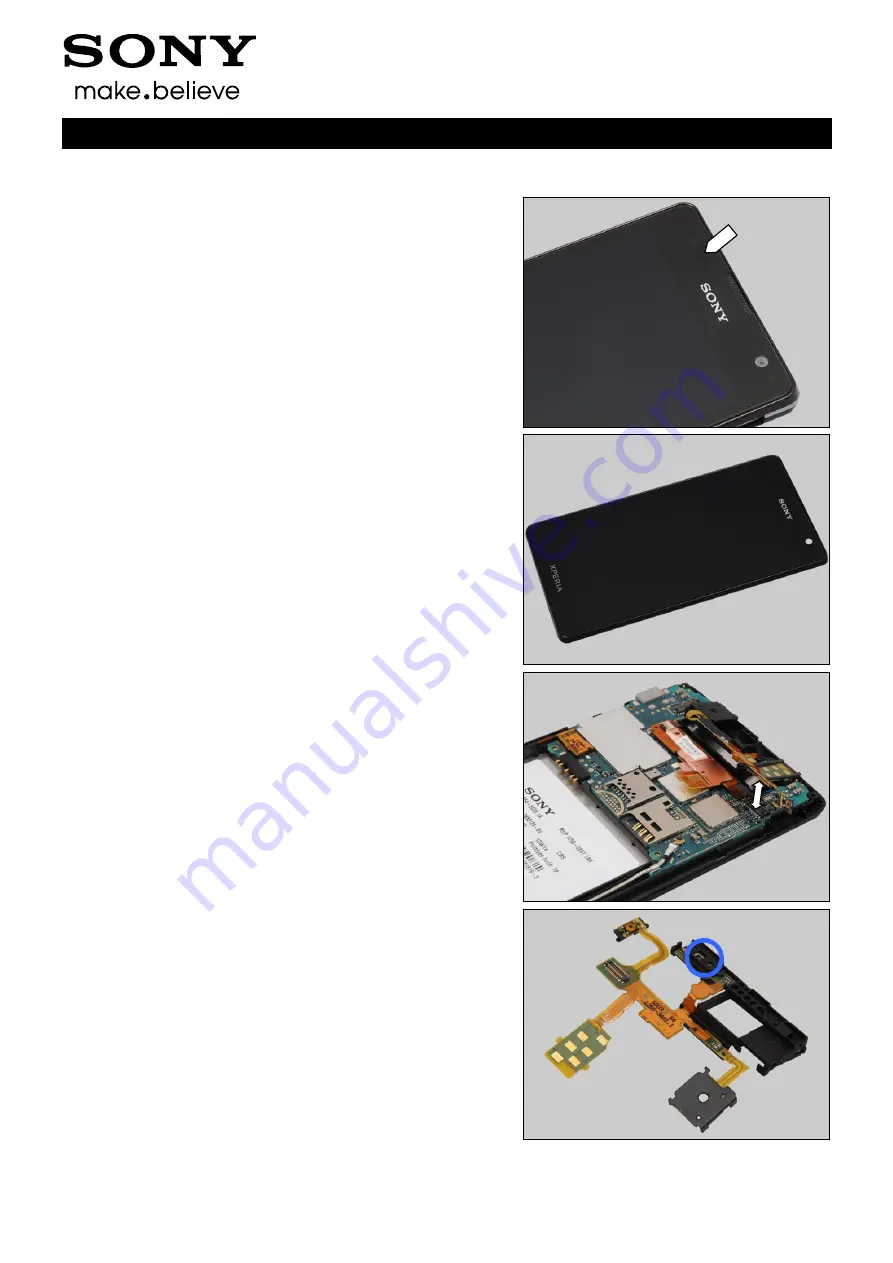
Inspect the proximity switch window area and the proximity 
sensor window area on the Cover Front Assy. 

Action: 

1. If dirty 

– clean it. 


2. If the end user has complained about unexpected 
behavior of the proximity sensor - Calibrate the P-sensor 
1262-6643 Trouble Shooting Application 

– mechanical. 

3. If scratched or damaged 

– replace the Cover Front Assy. 


Check: 

Inspect the BtB connector of the RCV Flex FPC to the PBA. 

Action: 

1. If not properly connected 

– disconnect and reconnect. 

2. If dirty or oxidized 

– clean it. 


Check: 

Inspect the proximity switch and proximity sensor on the 
RCV Flex FPC. 

Action: 

1. If dirty 

– clean it. 

2. If the BtB connector, the proximity switch or the proximity 
sensor of the RCV Flex FPC is damaged 

– replace the RCV 

Flex FPC. 

3. Replace board. 


Summary of Contents for Xperia TX LT29i

Page 1: ...1266 4901 Rev 1 Sony Mobile Communications AB Company Internal Working Instructions mechanical Xperia TX LT29i ...

Page 2: ...Label Core Unit 17 4 4 Water Indicator 18 4 5 Frame Rear Assy 19 4 6 Antenna NFC 20 4 7 Cushion 21 4 8 Audio Jack Adhesive Audio Jack 22 4 9 Vibrator 25 4 10 Loudspeaker Adhesive Speaker 26 4 11 Cap RF 28 4 12 Main Antenna Assy 30 4 13 Sub Antenna Assy 32 4 14 Key Camera 34 4 15 Key On Off 36 4 16 Key Volume 38 4 17 Camera 40 4 18 RCV Flex FPC 42 4 19 Ear Speaker Adhesive Earspeaker 49 4 20 Cushio...

Page 3: ... Change Label 67 4 31 Board Swap Customize of Software 67 5 Reassembly 68 5 1 Cover Front Assy Main PBA 68 5 2 RCV Flex FPC Assy 70 5 3 Camera 71 5 4 Key Flex FPC 72 5 5 Frame Rear Assy 74 5 6 Battery 76 5 7 Cover Battery Assy 76 6 Revision History 78 For general information about mechanical repair related issues refer to 1220 1333 Generic Repair Manual mechanical ...

Page 4: ...Working Instructions mech 1266 4901 Rev 1 Sony Mobile Communications AB Company Internal 4 78 1 Exterior Views 1 1 LT29i ...

Page 5: ...mpany Internal 5 78 2 Tools SPECIAL TOOLS 1 Torque Screwdriver 2 Front Opening Tool 3 Bits T5 4 Bits JCIS No 0 5 Flex Film Assembly Tool 6 Guitar Pick For part no s on the tools above refer to the Tools Catalogue Matrix STANDARD TOOLS 1 Dentist Hook 2 Nylon Pointer 3 Tweezers ...

Page 6: ...n the following order 1 Cover Battery Assy 2 Battery 3 Frame Rear Assy 4 Key Flex FPC 5 Camera 6 RCV Flex FPC Assy 7 Main PBA a Cover Front Assy b 3 1 Cover Battery Assy Gently pull upwards to unsnap the hooks of the Cover Battery Assy Remove the Cover Battery Assy 3 2 Battery Gently pull upwards to release the Battery with a finger ...

Page 7: ...it 3 3 Frame Rear Assy Remove the four Screw Other Len 4 0 Diam 1 4 by using a screwdriver with Bits T5 Scrap Not to be reused Remove the Screw 1 4X3 5 by using a screwdriver with Bits JCIS No 0 Scrap Not to be reused Remove the three Screw M1 4X3 0 by using a screwdriver with Bits JCIS No 0 Scrap Not to be reused ...

Page 8: ...s AB Company Internal 8 78 Disassembly There are twelve hooks securing the Frame Rear Assy Insert a Guitar Pick as shown in picture and gently slide along to release the hooks Do the same to release the bottom side Do the same to release the hooks on the opposite side ...

Page 9: ...y Mobile Communications AB Company Internal 9 78 Disassembly Do the same on the top side Remove the Frame Rear Assy 3 4 Key Flex FPC Disconnect the BtB connector of the Key Flex FPC by using a Front Opening Tool Disconnect the second BtB connector ...

Page 10: ...l 10 78 Disassembly Gently pull upwards to release the key camera switch as shown in picture by using a Front Opening Tool Remove the Key Flex FPC 3 5 Camera Disconnect the BtB connector of the Camera by using a Front Opening Tool Remove the Camera Be careful Do not touch the camera lens ...

Page 11: ...itch by using a Front Opening Tool as shown Disconnect the BtB connector Insert a Front Opening Tool as shown and gently pull upwards to release the RCV Flex FPC Assy from this side Be careful Do not damage the Cover Front Assy Do the same on the other side as shown in picture Be careful Do not damage the earspeaker mesh and the proximity sensor window of the Cover Front Assy ...

Page 12: ...bly Tool Scrap the RCV Flex FPC Assy Only the Ear Speaker can be reused Be careful Do not damage the earspeaker mesh and the proximity sensor window of the Cover Front Assy 3 7 Main PBA Cover Front Assy Disconnect the BtB connector by using a Front Opening Tool Disconnect the second BtB connector Disconnect this end of the RF Cable by using a Front Opening Tool ...

Page 13: ...y Internal 13 78 Disassembly Gently pull outwards to release the RF Cable from the hook of the Main PBA There are five hooks securing the Main PBA Insert a Flex Film Assembly Tool as shown in picture and gently pull upwards to release the hooks Do the same to release the Main PBA ...

Page 14: ...Working Instructions mech 1266 4901 Rev 1 Sony Mobile Communications AB Company Internal 14 78 Disassembly Remove the Main PBA ...

Page 15: ...he Removal as described below Prepare a new Label NFC Carry out the Installation as described below REMOVAL Carefully peel off the Label NFC by using a Flex Film Assembly Tool Scrap Not to be reused INSTALLATION Attach a new Label NFC on its proper position as indicated by the blue rectangle Press to secure its position and attachment ...

Page 16: ...1 Sony Mobile Communications AB Company Internal 16 78 Replacement 4 2 Cover Battery Assy Follow the 3 1 Disassembly instructions Prepare a new Cover Battery Assy Follow the 4 1 installation instructions Follow the 5 7 Reassembly instructions ...

Page 17: ...llow the 5 6 5 7 Reassembly instructions REMOVAL Read the old Mobile Phone Label and write the information into the Label Print Solution program before removal Carefully peel off the Label Core Unit by using a Flex Film Assembly Tool Scrap Not to be reused INSTALLATION Check that the label format is properly loaded in the Zebra printer and write a new Label using the Label Print Solution software ...

Page 18: ...ns Carry out the Removal as described below Prepare a new Water indicator Carry out the Installation as described below Follow the 5 6 5 7 Reassembly instructions REMOVAL Detach to remove the Water indicator Scrap Not to be reused INSTALLATION Place a new Water Indicator on the correct position as indicated by the guide line Press to secure its position and attachment ...

Page 19: ...ement 4 5 Frame Rear Assy Follow the 3 1 3 3 Disassembly instructions Follow the 4 8 4 9 4 10 4 11 4 14 4 15 and 4 16 Removal instructions Prepare a new Frame Rear Assy Follow the 4 6 4 7 4 8 4 9 4 10 4 11 4 12 4 13 4 14 4 15 and 4 16 Installation instructions Follow the 5 5 5 7 Reassembly instructions ...

Page 20: ...cribed below Prepare a new Antenna NFC Carry out the Installation as described below Follow the 4 7 Installation instructions Follow the 5 5 5 7 Reassembly instructions REMOVAL Detach to remove the Antenna NFC by using a Flex Film Assembly Tool Scrap Not to be reused INSTALLATION Place a new Antenna NFC on its proper position as indicated by the pegs and holes Press along to secure its position ...

Page 21: ... Removal as described below Prepare a new Cushion Carry out the Installation as described below Follow the 5 5 5 7 Reassembly instructions REMOVAL Detach to remove the Cushion by using a Flex Film Assembly Tool Scrap Not to be reused INSTALLATION Place a new Cushion on its proper position as indicated by the guiding rectangle Press along to secure its position and attachment ...

Page 22: ...he Removal as described below Prepare a new Audio Jack and a new Adhesive Audio Jack Carry out the Installation as described below Follow the 5 5 5 7 Reassembly instructions REMOVAL Insert a Nylon Pointer into the hole of the Audio Jack and gently pull upwards to release it from the cavity Remove it Detach to remove the Adhesive Audio Jack by using a Flex Film Assembly Tool Scrap Not to be reused ...

Page 23: ...e Communications AB Company Internal 23 78 Replacement Audio Jack Adhesive Audio Jack INSTALLATION Place a new Adhesive Audio Jack in the cavity Press to secure its attachment and position Peel off the protective film Place a new Audio Jack in the cavity ...

Page 24: ...structions mech 1266 4901 Rev 1 Sony Mobile Communications AB Company Internal 24 78 Replacement Audio Jack Adhesive Audio Jack Press to secure its attachment and position Be careful Do not touch the contact pins ...

Page 25: ...ns Carry out the Removal as described below Prepare a new Vibrator Carry out the Installation as described below Follow the 5 5 5 7 Reassembly instructions REMOVAL Lift up to remove the Vibrator from the cavity by using a Flex Film Assembly Tool INSTALLATION Place a new Vibrator in the cavity Press to secure its position Be careful Do not touch the contact pins ...

Page 26: ... Carry out the Removal as described below Prepare a new Loudspeaker and a new Adhesive Speaker Carry out the Installation as described below Follow the 5 5 5 7 Reassembly instructions REMOVAL Detach to remove the Loudspeaker from the cavity by using a pair of Tweezers Detach to remove the Adhesive Speaker Scrap Not to be reused INSTALLATION Place a new Adhesive Speaker in the cavity ...

Page 27: ... Internal 27 78 Replacement Loudspeaker Adhesive Speaker Press to secure its attachment Peel off the protective film Place it in the cavity Note the orientation of the Loudspeaker to be installed Press to secure its attachment and position Be careful Do not touch the contact pins ...

Page 28: ...ut the Removal as described below Prepare a new Cap RF Carry out the Installation as described below Follow the 5 6 5 7 Reassembly instructions There are two Cap RFs REMOVAL Gently insert the dentist hook underneath the Cap RF and remove it Be careful Do not damage the RF connector under the Cap RF INSTALLATION Place a new Cap RF in the hole as indicated by the pointer ...

Page 29: ...Working Instructions mech 1266 4901 Rev 1 Sony Mobile Communications AB Company Internal 29 78 Replacement Cap RF Press along to secure its position Do the same to the other if need ...

Page 30: ...Prepare a new Main Antenna Assy Carry out the Installation as described below Follow the 5 5 5 7 Reassembly instructions REMOVAL Push against the Main Antenna Assy from the back side of the Frame Rear Assy by using a Front Opening Tool as shown Turn the Frame Rear Assy over and lift up to remove the Main Antenna Assy Scrap Not to be reused INSTALLATION Place a new Main Antenna Assy on its proper p...

Page 31: ...Working Instructions mech 1266 4901 Rev 1 Sony Mobile Communications AB Company Internal 31 78 Replacement Main Antenna Assy Press to secure its attachment and position ...

Page 32: ...w Prepare a new Sub Antenna Assy Carry out the Installation as described below Follow the 5 5 5 7 Reassembly instructions REMOVAL Push against the Sub Antenna Assy from the back side of the Frame Rear Assy by using a Front Opening Tool as shown Turn the Frame Rear Assy over and lift up to remove the Sub Antenna Assy Scrap Not to be reused INSTALLATION Place a new Sub Antenna Assy on its proper pos...

Page 33: ...Working Instructions mech 1266 4901 Rev 1 Sony Mobile Communications AB Company Internal 33 78 Replacement Sub Antenna Assy Press to secure its attachment and position ...

Page 34: ...ry out the Removal as described below Prepare a new Key Camera Carry out the Installation as described below Follow the 5 5 5 7 Reassembly instructions REMOVAL Push against the Key Camera from the outside of the Frame Rear Assy as shown Remove the Key Camera INSTALLATION Place a new Key Camera into the slot as shown Note the orientation of the Key Camera to be installed ...

Page 35: ...nstructions mech 1266 4901 Rev 1 Sony Mobile Communications AB Company Internal 35 78 Replacement Key Camera Insert the rubber of the Key Camera into the hook of this side as shown Do the same to the other side ...

Page 36: ...ry out the Removal as described below Prepare a new Key On Off Carry out the Installation as described below Follow the 5 5 5 7 Reassembly instructions REMOVAL Push against the Key On Off from the outside of the Frame Rear Assy as shown Remove the Key On Off INSTALLATION Place a new Key On Off into the slot as shown Note the orientation of the Key On Off to be installed ...

Page 37: ...nstructions mech 1266 4901 Rev 1 Sony Mobile Communications AB Company Internal 37 78 Replacement Key On Off Insert the rubber of the Key On Off into the hook of this side as shown Do the same to the other side ...

Page 38: ...ry out the Removal as described below Prepare a new Key Volume Carry out the Installation as described below Follow the 5 5 5 7 Reassembly instructions REMOVAL Push against the Key Volume from the outside of the Frame Rear Assy as shown Remove the Key Volume INSTALLATION Place a new Key Volume into the slot as shown Note the orientation of the Key Volume to be installed ...

Page 39: ...nstructions mech 1266 4901 Rev 1 Sony Mobile Communications AB Company Internal 39 78 Replacement Key Volume Insert the rubber of the Key Volume into the hook of this side as shown Do the same to the other side ...

Page 40: ...3 Disassembly instructions Carry out the Removal as described below Prepare a new Camera Carry out the Installation as described below Follow the 5 5 5 7 Reassembly instructions uulg REMOVAL Disconnect the BtB connector of the Camera Remove the Camera Be careful Do not touch the camera lens INSTALLATION Place a new Camera in the socket ...

Page 41: ...rking Instructions mech 1266 4901 Rev 1 Sony Mobile Communications AB Company Internal 41 78 Replacement Camera Snap the BtB connector Press to secure its position Be careful Do not touch the camera lens ...

Page 42: ...w RCV Flex FPC Carry out the Installation as described below Follow the 4 17 Installation instructions Follow the 5 5 5 7 Reassembly instructions REMOVAL Insert a Front Opening Tool as shown and gently pull upwards to release the key on off switch by using a Front Opening Tool Disconnect the BtB connector Insert a Front Opening Tool as shown and gently pull upwards to release the RCV Flex FPC Assy...

Page 43: ...y sensor window of the Cover Front Assy Remove the RCV Flex FPC Assy by using a Flex Film Assembly Tool Scrap the RCV Flex Assy Only the Ear Speaker can be reused Be careful Do not damage the earspeaker mesh and the proximity sensor window of the Cover Front Assy Unsnap the hook of the RCV Flex FPC Assy Insert a Front Opening Tool as shown and gently pull upwards to release the Ear Speaker Scrap t...

Page 44: ...Company Internal 44 78 Replacement RCV Flex FPC INSTALLATION Prepare a new RCV Flex FPC and make sure the RCV Flex FPC to be pre bent as shown in picture Attach a new Adhesive Earspeaker in the cavity Press to secure its position and attachment Peel off the protective film ...

Page 45: ...ile Communications AB Company Internal 45 78 Replacement RCV Flex FPC Place the Ear Speaker in the cavity Press to secure its attachment and position Be careful Do not touch the contact pins Turn it over Press to snap the hook of the RCV Flex FPC Assy ...

Page 46: ...tions AB Company Internal 46 78 Replacement RCV Flex FPC Attach a new Cushion Audio Jack 2 on its proper position as shown Press along to secure its attachment and position Peel off the protective film Attach a new Cushion Audio Jack on its proper postion as shown ...

Page 47: ...4901 Rev 1 Sony Mobile Communications AB Company Internal 47 78 Replacement RCV Flex FPC Press to secure its attachment and position Place the new RCV Flex FPC Assy into the cavity Press to secure its position Snap the BtB connector ...

Page 48: ...Working Instructions mech 1266 4901 Rev 1 Sony Mobile Communications AB Company Internal 48 78 Replacement RCV Flex FPC Gently insert the key on off switch into its cavity Press to secure its position ...

Page 49: ...oval instructions Carry out the Removal as described below Prepare a new Ear Speaker and a new Adhesive Earspeaker Carry out the Installation as described below Follow the 4 17 Installation instructions Follow the 5 5 5 7 Reassembly instructions REMOVAL Insert a Front Opening Tool as shown and gently pull upwards to release the hook Detach to remove the Ear Speaker Detach to remove the Adhesive Ea...

Page 50: ...Communications AB Company Internal 50 78 Replacement Ear Speaker Adhesive Earspeaker INSTALLATION Attach a new Adhesive Earspeaker in the cavity Press to secure its position and attachment Peel off the protective film Place a new Ear Speaker in the cavity ...

Page 51: ...1 Rev 1 Sony Mobile Communications AB Company Internal 51 78 Replacement Earspeaker Adhesive Earspeaker Press to secure its attachment and position Be careful Do not touch the contact pins Press to snap the hook of the RCV Flex FPC Assy ...

Page 52: ...emoval as described below Prepare a new Cushion Audio Jack Carry out the Installation as described below Follow the 5 5 5 7 Reassembly instructions REMOVAL Detach to remove the Cushion Audio Jack by using a Flex Film Assembly Tool Scrap Not to be reused INSTALLATION Place a new Cushion Audio Jack on the proper position as indicated by the pointer Press to secure its attachment and position ...

Page 53: ...oval as described below Prepare a new Cushion Audio Jack 2 Carry out the Installation as described below Follow the 5 5 5 7 Reassembly instructions REMOVAL Detach to remove the Cushion Audio Jack 2 by using a Flex Film Assembly Tool Scrap Not to be reused INSTALLATION Place a new Cushion Audio Jack 2 on the proper position as indicated by the pointer Press to secure its attachment and position ...

Page 54: ...Working Instructions mech 1266 4901 Rev 1 Sony Mobile Communications AB Company Internal 54 78 Replacement Cushion Audio Jack 2 Peel off the protective film ...

Page 55: ...bly instructions Carry out the Removal as described below Prepare a new RF Cable Carry out the Installation as described below Follow the 5 5 5 7 Reassembly instructions REMOVAL Disconnect this end of the RF Cable Gently pull outwards to release the RF Cable from the hook of the Main PBA Do the same to release it from the hook of the Sub Board Assy ...

Page 56: ...obile Communications AB Company Internal 56 78 Replacement RF Cable Do the same to release it from the second hook Disconnect this end of the RF Cable and remove it INSTALLATION Prepare a new RF Cable and the front unit Snap this end of the RF Cable ...

Page 57: ...66 4901 Rev 1 Sony Mobile Communications AB Company Internal 57 78 Replacement RF Cable Push it into the hook of the Sub Board Assy Do the same to the second hook Connect this end of the RF Cable Push it into the hook of Main PBA ...

Page 58: ...ech 1266 4901 Rev 1 Sony Mobile Communications AB Company Internal 58 78 Replacement RF Cable Press along to insert the RF Cable into the socket by using a Front Opening Tool Push the RF Cable as shown to secure its position ...

Page 59: ...instructions Carry out the Removal as described below Prepare a new Cushion Key Flex Carry out the Installation as described below Follow the 5 5 5 7 Reassembly instructions REMOVAL Detach to remove the Cushion Key Flex Scrap Not to be reused INSTALLATION Attach a new Cushion Key Flex on its proper position as shown Press to secure its attachment and position ...

Page 60: ... 1 Sony Mobile Communications AB Company Internal 60 78 Replacement 4 24 Key Flex FPC Follow the 3 1 3 4 Disassembly instructions Prepare a new Key Flex FPC Follow the 4 23 Installation instructions Follow the 5 4 5 7 Reassembly instructions ...

Page 61: ...ibed below Prepare a new Sub Board Assy Carry out the Installation as described below Follow the 4 22 Installation instructions Follow the 5 4 5 7 Reassembly instructions REMOVAL There are two hooks securing the Sub Board Assy Insert a Front Opening Tool as shown and gently pull upwards to release the hook of this side Be careful Do not damage the Sub Board Assy Do the same on the other side Be ca...

Page 62: ...h 1266 4901 Rev 1 Sony Mobile Communications AB Company Internal 62 78 Replacement Sub Board Assy Remove it INSTALLATION Place a new Sub Board Assy in the cavity Press to snap the hooks Be careful Do not touch the contact pins ...

Page 63: ...below Prepare a new Cushion PBA Main Carry out the Installation as described below Follow the 5 1 5 7 Reassembly instructions REMOVAL Detach to remove the Cushion PBA Main by using a Front Opening Tool Be careful Do not damage the components Scrap Not to be reused INSTALLATION Place a new Cushion PBA Main on the PBA as indicated by the pointer and the guiding line Press to secure its attachment an...

Page 64: ...Removal as described below Prepare a new Sheet PBA Main Carry out the Installation as described below Follow the 5 1 5 7 Reassembly instructions REMOVAL Peel off the Sheet PBA Main by using Flex Film Assembly Tool Scrap Not to be reused INSTALLATION Place a new Sheet PBA Main on the PBA as indicated by the pointer and the guiding line Press along to secure its attachment and position ...

Page 65: ...Working Instructions mech 1266 4901 Rev 1 Sony Mobile Communications AB Company Internal 65 78 Replacement Sub Board Assy Do the same on the opposite side ...

Page 66: ...ollow the 3 1 3 7 Disassembly instructions Follow the 4 22 and 4 25 Removal instructions Prepare a new Cover Front Assy Follow the 4 25 and 4 22 Installation instructions Follow the 5 1 5 7 Reassembly instructions Proxy sensor calibration has to be performed for all replaced units 1262 6643 Trouble Shooting Application mechanical ...

Page 67: ...o initialize settings and wait 4 minutes before performs Customize Phone in Emma Proxy sensor calibration has to be performed for all replaced units 1262 6643 Trouble Shooting Application mechanical 4 30 Board Swap Change Label CHANGE LABEL Follow the instructions in the Generic Repair Manual Build swap for change of label 4 31 Board Swap Customize of Software CUSTOMIZE OF SOFTWARE Follow the inst...

Page 68: ...e following order 1 Cover Front Assy a Main PBA b 2 RCV Flex FPC Assy 3 Camera 4 Key Flex FPC 5 Frame Rear Assy 6 Battery 7 Cover Battery Assy 5 1 Cover Front Assy Main PBA Prepare the Cover Front Assy and the Main PBA Place the Main PBA on the Cover Front Assembly Press to snap the hooks Be careful Do not touch the pins on the Main PBA ...

Page 69: ...mmunications AB Company Internal 69 78 Reassembly Gently push against the RF Cable to snap it into the hook of the Main PBA Connect this end of the RF Cable Press along to insert the RF Cable into the socket Push the RF Cable as shown to secure its position ...

Page 70: ... Internal 70 78 Reassembly Snap the BtB connector with finger Snap the second BtB connector 5 2 RCV Flex FPC Assy Follow the 4 18 Removal and Installation instructions to replace a new RCV Flex FPC Assy Place the new RCV Flex FPC Assy in the cavity as shown Press to snap the hooks ...

Page 71: ...1266 4901 Rev 1 Sony Mobile Communications AB Company Internal 71 78 Reassembly Snap the BtB connector Gently insert the key on off switch into its cavity Press to secure its position 5 3 Camera Place the Camera into the socket ...

Page 72: ...1 Sony Mobile Communications AB Company Internal 72 78 Reassembly Snap the BtB connector Press to secure its position Be careful Do not touch the camera lens 5 4 Key Flex FPC Prepare the Key Flex FPC Securely place it into the socket as shown ...

Page 73: ... mech 1266 4901 Rev 1 Sony Mobile Communications AB Company Internal 73 78 Reassembly Snap the BtB connector Gently insert the key camera switch into its cavity Press to secure its position Snap the BtB connector as shown ...

Page 74: ... Mobile Communications AB Company Internal 74 78 Reassembly 5 5 Frame Rear Assy Place the Frame Rear Assy on the unit Press to snap the hooks Press to snap the hooks of this side Make sure the hooks securely snapped Do the same to the opposite side ...

Page 75: ... Communications AB Company Internal 75 78 Reassembly Do the same on the top side Do the same on the bottom side Apply 14 1 Ncm torque when tightening the three screws with Bits JCIS No 0 Apply 14 1 Ncm torque when tightening the screw with Bits JCIS No 0 ...

Page 76: ... Company Internal 76 78 Reassembly Apply 16 1 Ncm torque when tightening the four screws with Bits T5 5 6 Battery Insert the Battery into its socket Press the bottom of the Battery to secure its position 5 7 Cover Battery Assy Place the Cover Battery Assy on the front unit ...

Page 77: ...Working Instructions mech 1266 4901 Rev 1 Sony Mobile Communications AB Company Internal 77 78 Reassembly Press to snap the hooks ...

Page 78: ...Working Instructions mech 1266 4901 Rev 1 Sony Mobile Communications AB Company Internal 78 78 6 Revision History Rev Date Changes Comments 1 2012 Aug 31 Initial release ...

Page 79: ...1266 4996 Rev 1 Sony Mobile Communications AB Company Internal Repair Movies mechanical Xperia TX LT29i ...

Page 80: ...picture quality select Actual size or 100 as zoom level in Acrobat Reader To magnify while keeping an acceptable picture quality increase the zoom level to 200 If the movies appear to be jerky or blurred when viewing on line this is probably caused by the connection speed being too slow In that case right click with the mouse on the document name and select Save Target As to download the repair mo...

Page 81: ...Internal 3 4 1 Movies 1 1 Disassembly Cover Battery Assy Battery Frame Rear Assy Key Flex FPC Camera RCV Flex FPC Assy Main PBA a Cover Front Assy b 1 2 Reassembly Cover Front Assy a Main PBA b RCV Flex FPC Assy Camera Key Flex FPC Frame Rear Assy Battery Cover Battery Assy ...

Page 82: ...Repair Movies mech 1266 4996 Rev 1 Sony Mobile Communications AB Company Internal 4 4 2 Revision History Rev Date Changes Comments 1 2012 Aug 31 Initial release ...

Page 83: ...1266 5087 Rev 1 Sony Mobile Communications AB Company Internal Troubleshooting Guide mechanical LT29i Xperia TX ...

Page 84: ...Illumination 13 1 6 Speaker 15 1 6 1 Loudspeaker 15 1 7 Earphone 18 1 7 1 Earphone 18 1 8 Microphone 20 1 8 1 Microphone 20 1 8 2 Secondary Microphone 22 1 9 Vibrator 24 1 9 1 Vibrator not generating alerts 24 1 10 Camera 25 1 10 1 Camera defects 25 1 10 2 Video Call Camera defects 26 1 11 Flash LED 27 1 11 1 Flash LED not flashing 27 1 12 Bluetooth and WLAN 28 1 12 1 Bluetooth or WLAN connection ...

Page 85: ...Security fails 41 1 26 FM Radio 42 1 26 1 No Poor FM Radio reception 42 1 27 Flip slider counter 44 1 27 1 Flip slider counter fails 44 1 28 Verify Certificates 45 1 28 1 Verify certificates fails 45 1 29 IrDA Test 46 1 29 1 IrDA test fails 46 1 30 TV Out Test 47 1 30 1 TV Out test fails 47 1 31 Connector Ground Test 48 1 31 1 Connector ground test fails 48 1 32 Network Signal 49 1 32 1 No Poor si...

Page 86: ...ibrator is detected refer to section 1 4 Display Check Inspect the contact pads on the battery Action 1 If dirty or oxidized clean the pads 2 If damaged replace the battery Check Inspect the battery contact pins Action 1 If dirty or oxidized clean the contact pins 2 If adhesive is detected on the contact pins use an eraser to gently rub off the adhesive 3 If damaged replace board Check Inspect the...

Page 87: ... the Key On Off is damaged replace it Check Inspect the BtB connector of the RCV Flex FPC to the PBA Action 1 If not properly connected disconnect and reconnect 2 If dirty or oxidized clean it 3 If the key on off switch the BtB connector or the FPC of the RCV Flex FPC is damaged replace the RCV Flex FPC 4 Replace board ...

Page 88: ...1 2 1 Back Home and Multitask Keys Action 1 Refer to the section 1 3 Touch Screen 2 Replace board 1 2 2 Camera Key Check Inspect the external area of the Key Camera Action If dirty clean it Check Inspect the Key Camera a and the key camera switch b Action 1 If dirty clean them 2 If the Key Camera is damaged replace it ...

Page 89: ...nnected disconnect and reconnect 2 If dirty or oxidized clean the both sides of the BtB connector 3 If the key camera switch the BtB connector or the FPC of Key Flex FPC is damaged replace the Key Flex FPC 4 Replace board 1 2 3 Volume Key Check Inspect the external area of the Key Volume Action If dirty clean it Check Inspect the Key Volume a and the key volume switch b Action 1 If dirty clean the...

Page 90: ... damaged replace it 3 Replace board 1 2 4 On Off Key Check Inspect the Key On Off a and the key on off switch b Action 1 If dirty clean them 2 If the Key On Off is damaged replace it Check Inspect the BtB connector of the RCV Flex FPC to the PBA Action 1 If not properly connected disconnect and reconnect 2 If dirty or oxidized clean it ...

Page 91: ...e mech 1266 5087 Rev 1 Sony Mobile Communications AB Company Internal 9 57 Problem Areas Keys 3 If the key on off switch the BtB connector or the FPC of the RCV Flex FPC is damaged replace the RCV Flex FPC 4 Replace board ...

Page 92: ...een malfunction Check Inspect the touch screen Action If dirty clean it Check Inspect the BtB connector of the Cover Front Assy to the PBA Action 1 If not properly connected disconnect and reconnect 2 If dirty or oxidized clean it 3 If the touch screen or the FPC of the Cover Front Assy is damaged replace the Cover Front Assy 4 Replace board ...

Page 93: ... after the Key On Off has been pressed Action If the activation described above is not detected refer to section 1 1 Power Check Inspect the BtB connector of the Cover Front Assy to the PBA Action 1 If not properly connected disconnect and reconnect 2 If dirty or oxidized clean it 3 If the display or the FPC of the Cover Front Assy is damaged replace the Cover Front Assy 4 Replace board ...

Page 94: ... 1 5 LED Illumination 1 5 1 LED Illumination Check Inspect the external window area of the RGB LED on the Cover Front Assy Action 1 If dirty clean it 2 If the external window area is damaged replace the Cover Front Assy Check Inspect the RGB LED on the PBA Action 1 If dirty or clogged clean it 2 Replace board ...

Page 95: ...k Inspect the BtB connector of Key Flex FPC to the PBA Action 1 If not properly connected disconnect and reconnect 2 If dirty or oxidized clean the both sides of the BtB connector Check Inspect the BtB connector of Key Flex FPC to the Sub Board Assy Action 1 If not properly connected disconnect and reconnect 2 If dirty or oxidized clean the both sides of the BtB connector 3 If the two BtB connecto...

Page 96: ...ommunications AB Company Internal 14 57 Problem Areas Illumination Check Inspect the two LEDs on the Sub Board Assy Action 1 If dirty clean it 2 If the two LEDs or the BtB connector of the Sub Board Assy is damaged replace the Sub Board Assy 3 Replace board ...

Page 97: ...nspect the Loudspeaker s external port on the Cover Battery Assy Action 1 If the Loudspeaker external port is clogged clean it 2 If the Loudspeaker external port is damaged replace the Cover Battery Assy Check Inspect the mesh of the Loudspeaker on the Frame Rear Assy Action 1 If dirty clean it 2 If the mesh is damaged replace the Frame Rear Assy ...

Page 98: ...y Action 1 If dirty clean them 2 If the pins of the Loudspeaker are damaged replace the Loudspeaker Check Inspect the BtB connector of Key Flex FPC to the Sub Board Assy Action 1 If not properly connected disconnect and reconnect 2 If dirty or oxidized clean the both sides of the BtB connector 3 If the pads or the BtB connector of the Sub Board Assy is damaged replace the Sub Board Assy ...

Page 99: ...reas Speaker Check Inspect the BtB connector of Key Flex FPC to the PBA Action 1 If not properly connected disconnect and reconnect 2 If dirty or oxidized clean the both sides of the BtB connector 3 If the two BtB connectors or the FPC of the Key Flex FPC is damaged replace the Key Flex FPC 4 Replace board ...

Page 100: ...one 1 7 1 Earphone Check Inspect the Ear Speaker s external port on the Cover Front Assy Action 1 If clogged clean it 2 If the port is damaged replace the Cover Front Assy Check Inspect the Ear Speaker s pins and the pads on the RCV Flex FPC Action 1 If dirty clean them 2 If the pins are damaged replace the Ear Speaker ...

Page 101: ...57 Problem Areas Earphone Check Inspect the BtB connector of the RCV Flex FPC to the PBA Action 1 If not properly connected disconnect and reconnect 2 If dirty or oxidized clean it 3 If the pads the BtB connector or the FPC of the RCV Flex FPC is damaged replace the RCV Flex FPC 4 Replace board ...

Page 102: ...he port 2 If the port is damaged replace the Cover Front Assy Check Inspect the BtB connector of Key Flex FPC to the PBA Action 1 If not properly connected disconnect and reconnect 2 If dirty or oxidized clean the both sides of the BtB connector Check Inspect the BtB connector of Key Flex FPC to the Sub Board Assy Action 1 If not properly connected disconnect and reconnect 2 If dirty or oxidized c...

Page 103: ...m Areas Microphone 3 If the two BtB connectors or the FPC of Key Flex FPC is damaged replace the Key Flex FPC Check Inspect the microphone on the Sub Board Assy Action 1 If dirty clean it 2 If the microphone or the BtB connector of the Sub Board Assy is damaged replace the Sub Board Assy 3 Replace board ...

Page 104: ... Microphone Check Inspect the secondary microphone s external port on the Cover Battery Assy Action 1 If clogged clean the port 2 If the port is damaged replace the Cover Battery Assy Check Inspect the mesh of the secondary microphone on the Frame Rear Assy Action 1 If dirty clean it 2 If the mesh is damaged replace the Frame Rear Assy ...

Page 105: ...eshooting Guide mech 1266 5087 Rev 1 Sony Mobile Communications AB Company Internal 23 57 Problem Areas Microphone Check Inspect the secondary microphone on the PBA Action 1 If dirty clean it 2 Replace board ...

Page 106: ...r s pins and the pads on the RCV Flex FPC Action 1 If dirty or clogged clean them 2 If the Vibrator or its pins are damaged replace the Vibrator Check Inspect the BtB connector of the RCV Flex FPC to the PBA Action 1 If not properly connected disconnect and reconnect 2 If dirty or oxidized clean it 3 If the pads or the BtB connector is damaged replace the RCV Flex FPC 4 Replace board ...

Page 107: ...f camera window Action 1 If dirty clean it 2 If the camera window scratched or damaged replace the Frame Rear Assy Check Inspect the BtB connector of the Camera to the PBA Action 1 If not properly connected disconnect and reconnect 2 If dirty or oxidized clean both sides of the BtB connector Check Inspect the Camera Action 1 If the Camera is damaged replace it 2 Replace board ...

Page 108: ... 26 57 Problem Areas 1 10 2 Video Call Camera defects Check Inspect the external area of the video camera window Action 1 If dirty clean it 2 If scratched or damaged replace the Cover Front Assy Check Inspect the video camera on the PBA Action 1 If dirty or clogged clean it 2 Replace board ...

Page 109: ...s 1 11 Flash LED 1 11 1 Flash LED not flashing Check Inspect the external area of the flash LED window Action 1 If the flash LED window is dirty clean it 2 If the flash LED window scratched or damaged replace the Frame Rear Assy Check Inspect the flash LED on the PBA Action 1 If dirty clean it 2 Replace board ...

Page 110: ...Inspect the WLAN and Bluetooth antenna on the Sub Antenna Assy Action 1 If dirty clean it 2 If the antenna is damaged replace the Sub Antenna Assy Check Inspect the WLAN and Bluetooth antenna contact pads on the Sub Antenna Assy and the contact pins on the PBA Action 1 If dirty or oxidized clean the pads and pins 2 If the pads are damaged replace the Sub Antenna Assy 3 Replace board ...

Page 111: ...al 29 57 Problem Areas 1 13 NFC 1 13 1 NFC malfunctions Check Inspect the NFC antenna contact pads on the Antenna NFC and the contact pins on the PBA Action 1 If dirty or oxidized clean the pads and pins 2 If the Antenna FPC or its pads are damaged replace the Antenna NFC 3 Replace board ...

Page 112: ...spect the GPS antenna on the Sub Antenna Assy Action 1 If dirty clean it 2 If the antenna is damaged replace the Sub Antenna Assy Check Inspect the GPS antenna contact pads on the Sub Antenna Assy and the contact pins on the PBA Action 1 If dirty or oxidized clean the pads and pins 2 If the pads are damaged replace the Sub Antenna Assy 3 Replace board ...

Page 113: ...Troubleshooting Guide mech 1266 5087 Rev 1 Sony Mobile Communications AB Company Internal 31 57 Problem Areas 1 15 Compass 1 15 1 Compass fails Action Replace board ...

Page 114: ...Troubleshooting Guide mech 1266 5087 Rev 1 Sony Mobile Communications AB Company Internal 32 57 Problem Areas 1 16 Accelerometer 1 16 1 Accelerometer test fails Action Replace board ...

Page 115: ...Troubleshooting Guide mech 1266 5087 Rev 1 Sony Mobile Communications AB Company Internal 33 57 Problem Areas 1 17 Gyroscope 1 17 1 Gyroscope test fails Action Replace board ...

Page 116: ...ont Assy Action 1 If clogged clean it 2 If scratched or damaged replace the Cover Front Assy Check Inspect the BtB connector of the RCV Flex FPC to the PBA Action 1 If not properly connected disconnect and reconnect 2 If dirty or oxidized clean it Check Inspect the light sensor on the RCV Flex FPC Action 1 If dirty clean it 2 If the light sensor or the BtB connector of the RCV Flex FPC is damaged ...

Page 117: ...ehavior of the proximity sensor Calibrate the P sensor 1262 6643 Trouble Shooting Application mechanical 3 If scratched or damaged replace the Cover Front Assy Check Inspect the BtB connector of the RCV Flex FPC to the PBA Action 1 If not properly connected disconnect and reconnect 2 If dirty or oxidized clean it Check Inspect the proximity switch and proximity sensor on the RCV Flex FPC Action 1 ...

Page 118: ... Guide mech 1266 5087 Rev 1 Sony Mobile Communications AB Company Internal 36 57 Problem Areas 1 20 Pressure Sensor 1 20 1 Pressure Sensor test fails Action Not applicable This test is not applicable for this product ...

Page 119: ...leshooting Guide mech 1266 5087 Rev 1 Sony Mobile Communications AB Company Internal 37 57 Problem Areas 1 21 Water Proof 1 21 1 Water Proof fails Action Not applicable No water proof functions in the phone ...

Page 120: ...Troubleshooting Guide mech 1266 5087 Rev 1 Sony Mobile Communications AB Company Internal 38 57 Problem Areas 1 22 Real Time Clock 1 22 1 Real Time Clock test fails Action Replace board ...

Page 121: ...Troubleshooting Guide mech 1266 5087 Rev 1 Sony Mobile Communications AB Company Internal 39 57 Problem Areas 1 23 Total call time 1 23 1 Total call time fails Action Replace board ...

Page 122: ...xternal Memory 1 24 1 Memory Card not detected Check Inspect the external port of the memory card holder and check if a memory card can be properly inserted Action If dirty or clogged clean the external port Check Inspect the memory card holder on the PBA Action 1 If dirty or clogged clean the holder 2 Replace board ...

Page 123: ...Troubleshooting Guide mech 1266 5087 Rev 1 Sony Mobile Communications AB Company Internal 41 57 Problem Areas 1 25 Security 1 25 1 Security fails Action Replace board ...

Page 124: ...e Audio Jack Action If dirty or oxidized clean it Check Inspect the contact pins on the Audio Jack and the contact pads on the RCV Flex FPC Action 1 If dirty or oxidized clean the pads and pins 2 If the pins are damaged replace the Audio Jack Check Inspect the BtB connector of the RCV Flex FPC to the PBA Action 1 If not properly connected disconnect and reconnect 2 If dirty or oxidized clean it ...

Page 125: ...ing Guide mech 1266 5087 Rev 1 Sony Mobile Communications AB Company Internal 43 57 Problem Areas FM Radio 3 If the pads or the BtB connector of the RCV Flex FPC is damaged replace the RCV Flex FPC 4 Replace board ...

Page 126: ...oubleshooting Guide mech 1266 5087 Rev 1 Sony Mobile Communications AB Company Internal 44 57 Problem Areas 1 27 Flip slider counter 1 27 1 Flip slider counter fails Action Not applicable No slider phone ...

Page 127: ...Troubleshooting Guide mech 1266 5087 Rev 1 Sony Mobile Communications AB Company Internal 45 57 Problem Areas 1 28 Verify Certificates 1 28 1 Verify certificates fails Action Replace board ...

Page 128: ...Troubleshooting Guide mech 1266 5087 Rev 1 Sony Mobile Communications AB Company Internal 46 57 Problem Areas 1 29 IrDA Test 1 29 1 IrDA test fails Action Not applicable No IrDA in the phone ...

Page 129: ...ch 1266 5087 Rev 1 Sony Mobile Communications AB Company Internal 47 57 Problem Areas 1 30 TV Out Test 1 30 1 TV Out test fails Check Inspect the USB connector Action 1 If dirty or oxidized clean the connector 2 Replace board ...

Page 130: ...ide mech 1266 5087 Rev 1 Sony Mobile Communications AB Company Internal 48 57 Problem Areas 1 31 Connector Ground Test 1 31 1 Connector ground test fails Action Not applicable This test is not applicable for this product ...

Page 131: ...signal Check Inspect the sub antenna on the Sub Antenna Assy Action 1 If dirty clean it 2 If the pad is damaged replace the Sub Antenna Assy Check Inspect the main antenna contact pad on the Sub Antenna Assy and the contact pin on the PBA Action 1 If dirty or oxidized clean the pad and the pin 2 If the pad is damaged replace the Sub Antenna Assy ...

Page 132: ...e main antenna on the Main Antenna Assy Action 1 If dirty clean it 2 If the main antenna is damaged replace the Main Antenna Assy Check Inspect the main antenna contact pins on the Sub Board Assy and contact pads on the Main Antenna Assy Action 1 If dirty or oxidized clean the pads and pins 2 If the pads are damaged replace Main Antenna Assy ...

Page 133: ...the RF Cable to the Sub Board Assy Action 1 If not properly connected disconnect and reconnect it 2 If the connector or the pins of the Sub Board Assy is damaged replace the Sub Board Assy Check Inspect the connector of RF Cable to the PBA Action 1 If not properly connected disconnect and reconnect it 2 If the RF Cable is damaged replace it 3 Replace board ...

Page 134: ...k if a SIM card can be properly inserted Action If dirty or clogged clean the external port Check Inspect the SIM card holder on the PBA Action 1 If dirty or clogged clean the holder 2 Replace board 1 33 2 Incorrect SIM indicated Check Check whether the phone is locked to a particular operator and whether the correct operator SIM is being used Action 1 Use a proper operator SIM or test SIM 2 Repla...

Page 135: ...t pads of the Battery Action 1 If dirty or oxidized clean the pads 2 If damaged replace the Battery Check Inspect the battery contact pins Action 1 If dirty or oxidized clean the contact pins 2 If adhesive is detected on the contact pins use an eraser to gently rub off the adhesive Check Inspect the USB connector Action 1 If dirty or oxidized clean the connector 2 Replace board ...

Page 136: ...of the Audio Jack Action If dirty or oxidized clean the connector Check Inspect the contact pins on the Audio Jack and the contact pads on the RCV Flex FPC Action 1 If dirty or oxidized clean the pads and pins 2 If the pins are damaged replace the Audio Jack Check Inspect the BtB connector of the RCV Flex FPC to the PBA Action 1 If not properly connected disconnect and reconnect 2 If dirty or oxid...

Page 137: ...Guide mech 1266 5087 Rev 1 Sony Mobile Communications AB Company Internal 55 57 Problem Areas HandsFree by Wire 3 If the pads or the BtB connector of the RCV Flex FPC is damaged replace the RCV Flex FPC 4 Replace board ...

Page 138: ...v 1 Sony Mobile Communications AB Company Internal 56 57 Problem Areas 1 36 Data Communication 1 36 1 Data transfer via System Connector fails Check Inspect the USB connector Action 1 If dirty or oxidized clean the connector 2 Replace board ...

Page 139: ...Troubleshooting Guide mech 1266 5087 Rev 1 Sony Mobile Communications AB Company Internal 57 57 2 Revision History Rev Date Changes Comments 1 2012 Aug 31 Initial release ...

Page 140: ...1266 5128 Rev 2 Sony Mobile Communications AB Company Internal Test Instructions mechanical LT29i Xperia TX ...

Page 141: ... 2 10 Vibrator 10 2 2 11 Camera 10 2 2 12 Secondary Camera 10 2 2 13 Flash LED 11 2 2 14 Bluetooth 11 2 2 15 WLAN 12 2 2 16 NFC 12 2 2 17 GPS 12 2 2 18 Compass 13 2 2 19 Accelerometer 13 2 2 20 Gyroscope 14 2 2 21 Ambient Light Sensor 14 2 2 22 Proximity switch 15 2 2 23 Pressure Sensor 15 2 2 24 Water Proof 15 2 2 25 Real time clock 16 2 2 26 Total call time 16 2 2 27 Storage 16 2 2 28 Security 1...

Page 142: ...ia USB Charger or Computer 22 2 4 Battery Test 23 2 5 Network Test 24 2 5 1 On the air call to mobile no UMTS network available 24 2 5 2 On the air call to mobile UMTS network available 24 3 Revision History 25 For general information about test procedures refer to 1220 1333 Generic Repair Manual mechanical ...

Page 143: ...ater indicator inspection Before starting any tests the liquid intrusion indicator has to be checked The Water Indicator is located as shown in this picture after the Cover Battery Assy is removed If affected red color handle the phone according to the local directives If not affected by liquid proceed to the Pre Test Preparation below ...

Page 144: ...20 1333 Generic Repair Manual mechanical 1 2 1 2 Software version update Mandatory first repair action Use the USB cable to connect with the Micro USB connector of the phone for this purpose Ensure the phone is powered off and proceed as follows Open the Emma application and log in Press and hold the volume down key on the phone connect the phone to the USB cable and then release the volume down k...

Page 145: ...on 7378423 Sony Ericsson SONY XPERIA 1 2 3 4 5 6 7 8 9 0 Step 2 Select Service Tests Step 3 Select one of the tests and follow the test instructions as described below To stop the test and return to the Service Test Menu press the Back key For more information refer to 1220 1333 Generic Repair Manual mechanical Sony Ericsson SONY XPERIA Customization Settings Service Settings Service info Service ...

Page 146: ...2 2 2 Touch Screen Move a finger across the touch screen a line will be drawn as it touches Press the Back key to return to the Service Test Menu Sony Ericsson SONY XPERIA Touch Screen 2 2 3 Display Minor variations in the display s brightness and color may occur between phones There may be tiny bright dots on the display called defective pixels and which occur when individual dots have malfunctio...

Page 147: ...high strength all along Press the Back key to return to the Service Test Menu Sony Ericsson SONY XPERIA LED illumination 2 2 5 Speaker Do not hold the phone close to an ear during this test Make sure that the sound from the speaker port on the bottom back side of the phone is emitted loud and clear and that the test includes maximum volume Press the Volume Up Volume Down key to adjust the speaker ...

Page 148: ...he microphone during the Microphone Recording phase Step 2 Check the quality by listening to the recording from the Speaker during the Playing recorded sound phase at maximum volume Press the Back key to return to the Service Test Menu Sony Ericsson SONY XPERIA Media Volume Microphone test Microphone recording 2 2 9 Secondary Microphone The previous Speaker test must have been successfully carried...

Page 149: ... as an indication of a defective camera module Aim the camera located at the back of the phone at an object and check the quality of the image shown in the display Press the Key Camera to preview the photo s auto focus quality Photos are taken but not saved during this test Press the Back key to return to the Service Test Menu Sony Ericsson SONY XPERIA 2 2 12 Secondary Camera Minor variations in i...

Page 150: ...K There is a permission request select Yes Step 2 Search Step 3 Show the Device Found list Sony Ericsson SONY XPERIA An app on your phone wants to make your phone discoverable by other Bluetooth devices for 300 seconds Allow Yes Bluetooth permission request i Bluetooth Enable Bluetooth OK Searching Device found No Step 4 Select the Target Bluetooth Device and type the PIN code to pair Step 5 Type ...

Page 151: ...plete 2 2 16 NFC A NFC SIM card 3FF should be inserted in the phone before the start of this test The NFC test will be done in following sequences Step 1 Select NFC Step 2 NFC Diag Test Step 3 After Tag Reading Enabled can be seen on the display bring a NFC Tag close to the Label NFC on the Cover Battery Assy Don t touch each other to avoid Cover Battery Assy scratch Press the Back key two times t...

Page 152: ...procedures 2 2 19 Accelerometer The accelerometer test displays the actual position of the phone as a 3D coordinate X Y Z Press the Back key to return to the Service Test Menu Sony Ericsson SONY XPERIA Accelerometer X 0 1234 Y 6 7890 Z 0 1234 By tilting the phone in various directions the X Y Z values will change in size and polarity depending on the angle and direction as shown in the adjacent pi...

Page 153: ... 0 0001 Z Angular Speed 0 0001 Check Gravity Values Linear Acceleration Values Rotation Vector Values and Gyroscope Values by moving the phone Gravity Values can be refer to Accelerometer Linear Acceleration Values and Rotation Vector Values are in accordance with the action shown in the picture Gyroscope Values are updated while moving the phone Press the Back key to return to the Service Test Me...

Page 154: ...rent type of tone Press the Back key to return to the Service Test Menu Sony Ericsson SONY XPERIA Proximity switch ON 2 2 23 Pressure Sensor Not applicable do not use This test is not available for this product Sony Ericsson SONY XPERIA Water Proof This device does not support the function This device does not support the function Proximity switch Ambient Light Sensor Accelerometer Compass Gyrosco...

Page 155: ...he Back key to return to the Service Test Menu Sony Ericsson SONY XPERIA Total call time 00 01 07 2 2 27 Storage Memory Storage status Internal Mass Storage is Inserted Mounted as shown on the screen A memory card should be inserted in the phone before starting this test External Storage SD Card is Inserted as shown on the screen Attach USB Adaptor between phone and an USB disk as shown in picture...

Page 156: ... OK Active 2 2 29 FM Radio Verify that the phone can detect a radio station Connect a headset and then set your local radio station in Hz Verify that the reception and sound quality is normal Press the Back key to return to the Service Test Menu Sony Ericsson SONY XPERIA Set 98000 1 2 FM Radio example 98000 Hz 2 2 30 Battery Health test Not applicable do not use This test is not available for this...

Page 157: ...ertificates Not applicable do not use When entering the test four information categories will be shown Media Shared Platform and Application Press the Back key to return to the Service Test Menu Sony Ericsson SONY XPERIA Using dummy applications 2 2 33 IrDA Test Not applicable do not use This test is not available for this product Sony Ericsson SONY XPERIA TV Out Test IrDA Test IrDA Test app doesn...

Page 158: ...olutions under TV Out Settings Sony Ericsson SONY XPERIA TV Out On TV Out Settings TV Out Test Step 1 Attach cable between phone and TV Out as shown in picture Step 2 Press Play Video HDMI Type A cable TV Out MHL Adapter Micro USB Cable Charger PC Sony Ericsson SONY XPERIA Play Video Get TV Out Status EDID Reading TV Out Off Receive a test tone and a red green blue test picture in the TV Out Monit...

Page 159: ...ts Press Get TV Out Status You should now get Power Status Active HPD Status H RSEN Status H TDMS Status On HDCP Status On CEC Status Idle Press the Back key to return to the Service Test Menu Sony Ericsson SONY XPERIA Power Status Active HPD Status H RSEN Status H TDMS Status On HDCP Status On CEC Status Idle ...

Page 160: ...l be displayed above the Time Clock when phone is in Lock status If not detected the message Emergency call only will be displayed instead in the pull down Status Bar Press Back key to return to Standby Menu Sony Ericsson SONY XPERIA Notifications Operator name 2 3 2 On Off key test Press the Key On Off for a long time to turn the phone on or off Press the Key On Off for a short time to enter Slee...

Page 161: ...cation such as PC Suite or Emma is active Do not start the phone Connect a USB cable from a computer or charger to the phone Verify that the phone is being charged by the notification LED and Battery icon in the display Remove the USB cable from the connector and verify that the notification LED and Battery icon no longer indicates charging Sony Ericsson SONY XPERIA The Notification LED colour sta...

Page 162: ...he phone or with the charger The guide will describe different procedures depending on the battery level when the battery test is initiated The test is downloaded to the phone using cable or Bluetooth and executed The test is available in CSPN at Level Mechanical Title Trouble Shooting Application 1266 2711 Unzip this file where you find the application installation and user guide content The Char...

Page 163: ...and check the sound quality in both phones Step 5 Adjust the volume up and down with the side keys and verify that the sound level is altered Step 6 End the call and check that the elapsed time is displayed and that the termination is done properly 1 2 4 Sony Ericsson SONY XPERIA 5 Current call 00 01 Earphone In call volume 0001234567800 End Call 3 6 2 5 2 On the air call to mobile UMTS network av...

Page 164: ...nstructions mech 1266 5128 Rev 2 Sony Mobile Communications AB Company Internal 25 25 3 Revision History Rev Date Changes Comments 1 2012 Aug 31 Initial release 2 2012 Sep 14 Add 2 4 battery test application ...

Page 165: ...1266 5132 Rev 1 Sony Mobile Communications AB Company Internal Part List mechanical LT29i Xperia TX ...

Page 166: ...Part List mech 1266 5132 Rev 1 Sony Mobile Communications AB Company Internal 2 8 CONTENTS 1 Part List 3 2 Revision History 8 ...

Page 167: ...ir Movies and Troubleshooting Guide are often referred to by a simple descriptive name for better understanding Both names designations will in that case be included in this Part List where the name being used in the documents mentioned above is underlined e g Battery Cover Designation Part No Part Location Adhesive Audio Jack 1257 4105 Adhesive Earspeaker 1257 6217 Adhesive Speaker 1257 4292 Ante...

Page 168: ... Black Cover Battery Assy Pink Cover Battery Assy White 1262 2001 1257 7349 1262 2003 Cover Front Assy Cover Front Assy Black Cover Front Assy Pink Cover Front Assy White 1264 5358 1264 5360 1264 5359 Cushion 1263 3122 Cushion Audio Jack 1257 6447 Cushion Audio Jack 2 1262 1946 Cushion Key Flex 1264 5252 Cushion PBA Main 1263 4759 Ear Speaker 1226 7255 ...

Page 169: ...08 Key Camera Key Camera Black Key Camera Pink Key Camera White 1257 4370 1257 7345 1257 7344 Key Flex FPC 1255 3630 Key On Off Key On Off Black Key On Off Pink Key On Off White 1257 4357 1257 7337 1257 7334 Key Volume Key Volume Black Key Volume Pink Key Volume White 1257 4366 1257 7341 1257 7340 Label Core Unit 1257 6453 Label NFC Label NFC Black Label NFC White 1263 1518 1264 6322 Loudspeaker L...

Page 170: ...ompany Internal 6 8 Designation Part No Part Location Main Antenna Assy 1257 3743 RCV Flex FPC 1255 3601 RF Cable 1257 7339 Screw 1 4X3 5 1262 1965 Screw M1 4X3 0 1262 3150 Screw Other Len 4 0 Diam 1 4 1227 2716 Sheet PBA Main 1261 4181 Sub Antenna Assy 1257 3759 ...

Page 171: ...Part List mech 1266 5132 Rev 1 Sony Mobile Communications AB Company Internal 7 8 Designation Part No Part Location Sub Board Assy 1264 5365 Vibrator 1245 2711 Water Indicator 1257 4189 ...

Page 172: ...Part List mech 1266 5132 Rev 1 Sony Mobile Communications AB Company Internal 8 8 2 Revision History Rev Date Changes Comments 1 2012 Aug 31 Initial release ...

Page 173: ...1266 5133 Rev 1 Sony Mobile Communications AB Company Internal Go No Go Test electrical LT29i ...

Page 174: ...Mobile Communications AB Company Internal 2 8 CONTENTS 1 Go No Go Testing 3 1 1 Antenna Coupler 3 1 2 Direct Line 4 1 3 Attenuation Factors 6 1 3 1 Loss Values Antenna Coupler 6 1 3 2 Loss Values Direct Line 7 2 Revision History 8 This product is ONLY implemented in SERP II ...

Page 175: ...ue Matrix 1 1 Antenna Coupler The following equipment has to be used Rohde Schwartz RF Shield Package Rohde Schwartz RF Shield Box Rohde Schwartz RF Coupler Grid Positioning Holder RF Test Cable Flexible 1M RF Adapter for RF Shield Box Micro USIM Card instrument specific GSM 850 900 1800 1900 WCDMA 850 900 1700 1900 2100 Put the grid positioning holder with its reference point in position G12 and ...

Page 176: ... Go NoGo Testing 1 2 Direct Line The following equipment has to be used RF Test Cable Flexible 1M RF Probe Micro USIM Card instrument specific Connect the RF Probe as shown in the adjacent picture To get access to the RF connector on the PBA refer to 1266 4901 LT29i Mechanical Working Instructions Chapter 3 1 and 4 11 ...

Page 177: ...5 8 Go NoGo Testing Follow the directions stated in Go NoGo Test Script Parameters to be found in 1220 1336 Generic Repair Manual electrical together with the Attenuation Factors below This phone is available in one version LT29i including the following bands LT29i GSM 850 900 1800 1900 WCDMA 850 900 1700 1900 2100 ...

Page 178: ... 3 1 Loss Values Antenna Coupler Attenuation LT29i Band Channel Rx Tx GSM 850 Low 8 14 06 Mid 5 9 91 High 6 8 95 GSM 900 Low 4 6 55 Mid 4 8 36 High 4 8 45 GSM 1800 Low 11 11 55 Mid 11 9 73 High 11 9 41 GSM 1900 Low 14 13 78 Mid 15 14 96 High 14 15 88 WCDMA 850 Low 7 8 89 Mid 8 8 14 High 7 7 31 WCDMA 900 Low 6 6 19 Mid 7 5 2 High 7 4 88 WCDMA 1700 Low 12 5 11 77 Mid 12 12 14 High 12 9 88 WCDMA 1900...

Page 179: ... Internal 7 8 Go NoGo Testing Attenuation Factors 1 3 2 Loss Values Direct Line Attenuation Band Channel Rx Tx GSM 850 All 1 0 1 0 GSM 900 All 1 0 1 0 GSM 1800 All 2 3 2 3 GSM 1900 All 2 3 2 3 WCDMA 850 All 2 5 2 5 WCDMA 900 All 2 5 2 5 WCDMA 1700 All 1 3 1 3 WCDMA 1900 All 1 3 1 3 WCDMA 2100 All 1 3 1 3 ...

Page 180: ...Test and Calibration Repair Instruction Electrical 1266 5133 Rev 1 Sony Mobile Communications AB Company Internal 8 8 2 Revision History Rev Date Changes Comments 1 2012 Aug 28 Initial release ...

Page 181: ...1266 5131 Rev 1 Sony Mobile Communications AB Company Internal Customization build swap XperiaTX LT29i ...

Page 182: ...nal 2 7 CONTENTS 1 Emma Login Script Execution 3 2 Customization Workflow 4 2 1 Customize Unit 5 2 2 Customize to Ship or Build Swap 6 2 2 1 Customize to Ship 6 2 2 2 Build Swap 6 3 Revision History 7 For general information about Customization and Swap refer to 1221 5655 Generic Repair Manual build swap ...

Page 183: ... Instruction Build Swap Sony Mobile Communications AB Company Internal Emma Login Script Execution In order to change a phone from Customer A to Customer B you must run a Customization Script Start by launching the Emma application USB cable to one of the connect the cable to has to be inserted into one of the computer s USB ports to be able to log in Activation you need to be properly logged on t...

Page 184: ...Customization Repair Instruction Build Swap 1266 5131 Rev 1 Sony Mobile Communications AB Company Internal 4 7 2 Customization Workflow ...

Page 185: ...look for the Customize script for the desired Sales Item if that script is not available locally select Server search for a complete list of available scripts When creating a build swap unit select LT29 Service Exchange Unit as the customization scripts choose the desired script the application will download all necessary software to run the script and then flash that software to the phone after s...

Page 186: ... the Exchange Unit Box LabelMake instructions to be found on CSPN under LabelMake 2 2 1 2 Customize Mechanics If necessary apply the proper custom mechanical parts co branding keyboard etc for the variant being created in accordance with the Cross Reference List by following the instructions of 1266 4901 Working Instructions mechanical 2 2 2 Build Swap 2 2 2 1 Label Unit Using a red marker label t...

Page 187: ...Customization Repair Instruction Build Swap 1266 5131 Rev 1 Sony Mobile Communications AB Company Internal 7 7 3 Revision History Rev Date Changes Comments 1 2012 Aug 31 Initial release ...

Reviews: