


8
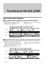
Overview
XCL-X700/V500
6
5
Rear
5
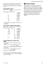
DC IN (DC power input) connector (12-pin)
6
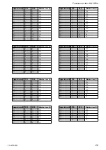
DIGITAL IF (Interface) connector (26-pin)
5
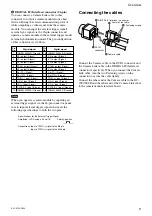
DC IN (DC power input) connector (12-pin)
You can connect a CCXC-12P05N camera cable to
input the +12 V DC power supply. When a sync signal
generator is connected to this connector, the camera
module is synchronized with the external sync signals.
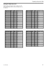
The pin configuration of this connector is as follows.
Pin No.
Camera sync output
External Sync mode (HD/VD)
Restart reset
External trigger shutter
1
Ground
Ground
Ground
Ground
2
+12 V DC
+12 V DC
+12 V DC
+12 V DC
3
—
—
—
—
4
Clock (+) input (Signal)
Clock (+) input (Signal)
Clock (+) input (Signal)
Clock (+) input (Signal)
5
HD output (Ground)
HD input (Ground)
HD input (Ground)
HD input (Ground)
6
HD output (Signal)
HD input (Signal)
HD input (Signal)
HD input (Signal)
7
VD output (Signal)
VD input (Signal)
Reset (Signal)
VD input (Signal)
8
—
—
—
—
9
Clock (–) input (Signal)
Clock (–) input (Signal)
Clock (–) input (Signal)
Clock (–) input (Signal)
10
—
—
—
WEN output (Signal)
11
—
—
—
Trigger pulse input (Signal)
12
VD output (Ground)
VD input (Ground)
Reset (Ground)
VD input (Ground)
Note
When you operate a camera module by inputting an
external clock signal, input the external signal using
the VIDEO connectors of the DC-700. Make sure to
input external clock signals that meet the following
specifications to both connectors.
Specifications for the external clock signal
Amplitude: LVDS (Low-Voltage Differential Signaling)
system using a 3.3 volt IC.
Frequency:
XCL-X700: 29.5 MHz to 59.0 MHz
XCL-V500: 24.545 MHz to 49.09 MHz
Connections: Input a CLOCK (+) signal to the VIDEO 1
connector of the DC-700.
Input a CLOCK (–) signal to the VIDEO 2
connector of the DC-700.