


KE-50XBR900(UC)
3
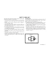
LEAKAGE TEST
The AC leakage from any exposed metal part to earth ground and from all
exposed metal parts to any exposed metal part having a return to chassis,
must not exceed 0.5 mA (500 microamperes).
Leakage current can be measured by any one of three methods.
1. A commercial leakage tester, such as the Simpson 229 or RCA WT-
540A. Follow the manufacturers’ instructions to use these instruments.
2. A battery-operated AC milliammeter. The Data Precision 245 digital
multimeter is suitable for this job.
3. Measuring the voltage drop across a resistor by means of a VOM or
battery-operated AC voltmeter. The “limit” indication is 0.75 V, so
analog meters must have an accurate low-voltage scale. The Simpson 250
and Sanwa SH-63Trd are examples of a passive VOMs that are suitable.
Nearly all battery operated digital multimeters that have a 2 V AC range
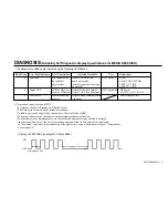
are suitable. (See Fig. A)
Fig. A. Using an AC voltmeter to check AC leakage.
1.5 k
Ω
0.15
µ
F
AC
Voltmeter
(0.75 V)
To Exposed Metal
Parts on Set
Earth Ground
SAFETY CHECK-OUT
After correcting the original service problem, perform the following safety
checks before releasing the set to the customer:
1. Check the area of your repair for unsoldered or poorly-soldered
connections. Check the entire board surface for solder splashes and
bridges.
2. Check the interboard wiring to ensure that no wires are “pinched” or
contact high-wattage resistors.
3. Check that all control knobs, shields, covers, ground straps, and
mounting hardware have been replaced. Be absolutely certain that you
have replaced all the insulators.
4. Look for unauthorized replacement parts, particularly transistors, that
were installed during a previous repair. Point them out to the customer
and recommend their replacement.
5. Look for parts which, though functioning, show obvious signs of
deterioration. Point them out to the customer and recommend their
replacement.
6. Check the line cords for cracks and abrasion. Recommend the
replacement of any such line cord to the customer.
7. Check the connector shell, metal trim, “metallized” knobs, screws, and
all other exposed metal parts for AC Leakage. Check leakage as de-
scribed right.
Summary of Contents for WEGA KE-50XBR900, KE-42XBR900
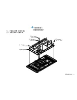
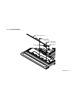
Page 18: ...KE 50XBR900 UC 1 9 1 2 3 H4 BOARD REMOVAL 1 Two screws BVTP 3X12 2 H4 Board Front panel ...
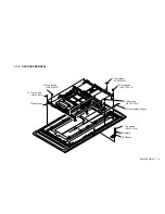
Page 19: ...KE 50XBR900 UC 1 10 1 2 4 H3 BOARD REMOVAL 1 Three screws BVTP 3X12 2 H3 Board Front panel ...
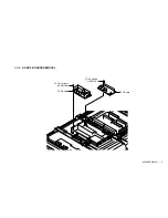
Page 21: ...KE 50XBR900 UC 1 12 1 2 6 H2 BOARD REMOVAL 1 Two screws M 3X8 P SW 2 H2 Board ...
Page 23: ...KE 50XBR900 UC 1 14 1 2 8 B BLOCK ASSY REMOVAL 1 B Block assy ...
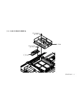
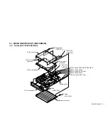
Page 24: ...KE 50XBR900 UC 1 15 1 2 9 M AD AND AU BOARDS REMOVAL 2 Shield case 1 Screw PSW 3x8 ...
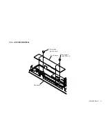
Page 28: ...KE 50XBR900 UC 1 19 1 2 13 U1 BOARD REMOVAL 1 Four screws BVTP 3x12 2 U1 Board 3 Core FPC ...
Page 29: ...KE 50XBR900 UC 1 20 1 2 14 U2 BOARD REMOVAL 1 Tow screws BVTP 3x12 2 U2 Board Rear panel ...