KE-50XBR900(UC)
2-2
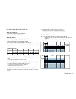
• Measuring procedure
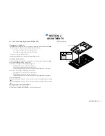
1. Dab the W/B adjustment jig (CA-100) at the glass face of the panel.
2. Connect the Signal generator (VG-828D) to the DVI terminal.
3. Input All-white signal and set the picture mode to DYNAMIC.
4. Select”PNLCTRL” in the service mode menu and set “0 WBNO” at “0”
5. Select “SCNR” “SCNB” of “PDPWB” in the service mode menu, and then adjust following
W/B standardized values of 6500K, 8000K, 9300K, 10000K and 13550K to following values
of X/Y.
6. After adjusting the values, at the values of the “SCNR” or “SCNB” exceeding 128 (initialize
value).
1)Reset a lager value of the “SCNR” or “SCNB” at 128.
2)Set the White Balances with the last of items and “SCNG” to the X/Y values above.
7. After the above step, when these item are nonqualified following conditions, set the largest
one at 128 and readjust the White Balance with the last two item.
1)No one of “SCNR”, “SCNB” and “SCNG” exceeding 128
2)Confirm the item value 128 at least one item
8. As a result above, input the sequential number of value to the “SCNR”, “SCNB” and
“SCNG”.
9. Repeat the same step 5 thru 8 for the W/B 1 thru 4 after setting the “0 WBNO” at each W/B
number.
6500K+8MPCD 8000K+8MPCD 9300K+8MPCD
10000K
13550K
W/B
0
1
2
3
4
X
0.3133
±
0.003
0.2944
±
0.003
0.2838
±
0.003
0.2806
±
0.003 0.2684
±
0.003
Y
0.3297
±
0.003
0.3100
±
0.003
0.2981
±
0.003
0.2883
±
0.003 0.2700
±
0.003
W/B standardized values:
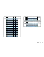
2-2. White Balance Adjustment (PDM-5000)
• Measurement equipment
1.Color analyzer (CA-100 manufactured by MINOLTA)
1.Signal generator (ASTRO DESIGN VG-828D)
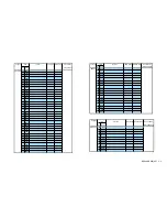
• Service mode lists
Caution: 1. Setting functions of Display section are displayed with yellow OSD.
2. Be careful not to set DATA in the yellow-covered OSD menu. The setting will be
memorized.
3. items are not required adjustment or are banned adjustment
10.Input following signals from the Signal generator (VG-828D).
1)All-white signal (255/255) input Y (luminance)=45cd/m
2
or more
2)1/25Window (255/255) input
Y (luminance)=45cd/m
2
or more
Category
Item
Function
Data range Initialize value
Device Name
No. Name
(Slave Address)
PDPWB
00 SCNR Sub contrast RED gain
0-255
128
CXD9738R
01 SCNG Sub contrast GREEN gain
0-255
128
02 SCNB Sub contrast BLUE gain
0-255
128
03 SBRR Sub brightness RED
0-255
128(Fix)
04 SBRG Sub brightness GREEN
0-255
127(Fix)
05 SBRB Sub brightness BLUE
0-255
128(Fix)
Category
Item
Function
Data range Initialize value
Device Name
No. Name
(Slave Address)
PDPSHAP 00 CRMD
01
HTAP
02
VTAP
03 AGCM
04
EDDL
05 EDGA
06 EDNM
07
EDDE
08
DHVS
Summary of Contents for WEGA KE-50XBR900, KE-42XBR900
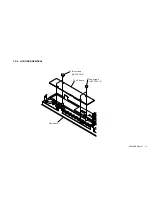
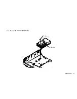
Page 18: ...KE 50XBR900 UC 1 9 1 2 3 H4 BOARD REMOVAL 1 Two screws BVTP 3X12 2 H4 Board Front panel ...
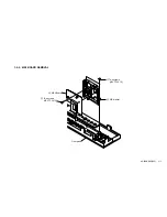
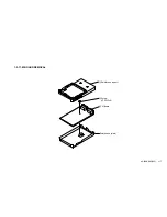
Page 19: ...KE 50XBR900 UC 1 10 1 2 4 H3 BOARD REMOVAL 1 Three screws BVTP 3X12 2 H3 Board Front panel ...
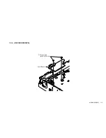
Page 21: ...KE 50XBR900 UC 1 12 1 2 6 H2 BOARD REMOVAL 1 Two screws M 3X8 P SW 2 H2 Board ...
Page 23: ...KE 50XBR900 UC 1 14 1 2 8 B BLOCK ASSY REMOVAL 1 B Block assy ...
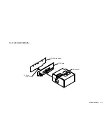
Page 24: ...KE 50XBR900 UC 1 15 1 2 9 M AD AND AU BOARDS REMOVAL 2 Shield case 1 Screw PSW 3x8 ...
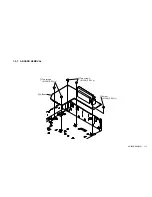
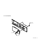
Page 28: ...KE 50XBR900 UC 1 19 1 2 13 U1 BOARD REMOVAL 1 Four screws BVTP 3x12 2 U1 Board 3 Core FPC ...
Page 29: ...KE 50XBR900 UC 1 20 1 2 14 U2 BOARD REMOVAL 1 Tow screws BVTP 3x12 2 U2 Board Rear panel ...

