Adjusting
30
1
Loosen the image surface adjustment fixing screw
D by turning it to the left several times.
2
Adjust the focus of the projection lens at the left of
the projected surface (or at the projected surface
near the image surface adjustment screw C) using
the button on the remote control or the projector.
3
Check the right of the projected surface (or at the
projected surface further from the image surface
adjustment screw C), and confirm if the focus
position is in front of the projected surface or at the
far back of the projected surface.
4
Adjust the position of the image surface to adjust
the focus on the right of the projected surface.
When the image surface confirmed in step 3 is in
front of the projected surface, turn the image
surface adjustment screw C to the right. When the
image surface confirmed in step 3 is at the far back
of the projected surface, turn the image surface
adjustment screw C to the left.
5
Adjust the position of the image surface by
repeating steps 2 to 4 so that the focus can be
adjusted in all positions.
6
When the adjustment is finished, turn the image
surface adjustment fixing screw D to the right and
tighten the screw until it is fixed.
Confirmation method of the default
position of the image surface
For the positions of the default image surface pin A and
B, see the illustration on page 24. For the positions of
the image surface adjustment screw A and C, and image
surface adjustment fixing screw B and D, see the
illustrations on page 29.
Confirmation method of the default
position of the vertical image surface
1
Loosen the image surface adjustment fixing screw
B by turning it to the left several times.
2
Turn the image surface adjustment screw A to the
right until the default image surface pin A of the
ceiling side can be inserted.
3
Insert the default image surface pin A of the ceiling
side straightly as far as it will go.
If the pin is not inserted fully, repeat steps 1 and 2.
4
Turn the image surface adjustment screw A to the
left until the default image surface pin A is fixed
firmly.
You can confirm the default position of the image
surface.
Confirmation method of the default
position of the horizontal image surface
1
Loosen the image surface adjustment fixing screw
D by turning it to the left several times.
2
Turn the image surface adjustment screw C to the
right until the default image surface pin B of the
side of the projection lens can be inserted.
3
Insert the default image surface pin B of the side of
the projection lens straightly as far as it will go.
If the pin is not inserted fully, repeat steps 1 and 2.
4
Turn the image surface adjustment screw C to the
left until the default image surface pin B is fixed
firmly.
You can confirm the default position of the image
surface.
Notes
• If the image surface adjustment fixing screws are
loosen too much, the screws may fall and be lost.
• Remove the default image surface pins before use. For
details, see “Removing the default image surface
pins” (page 24).
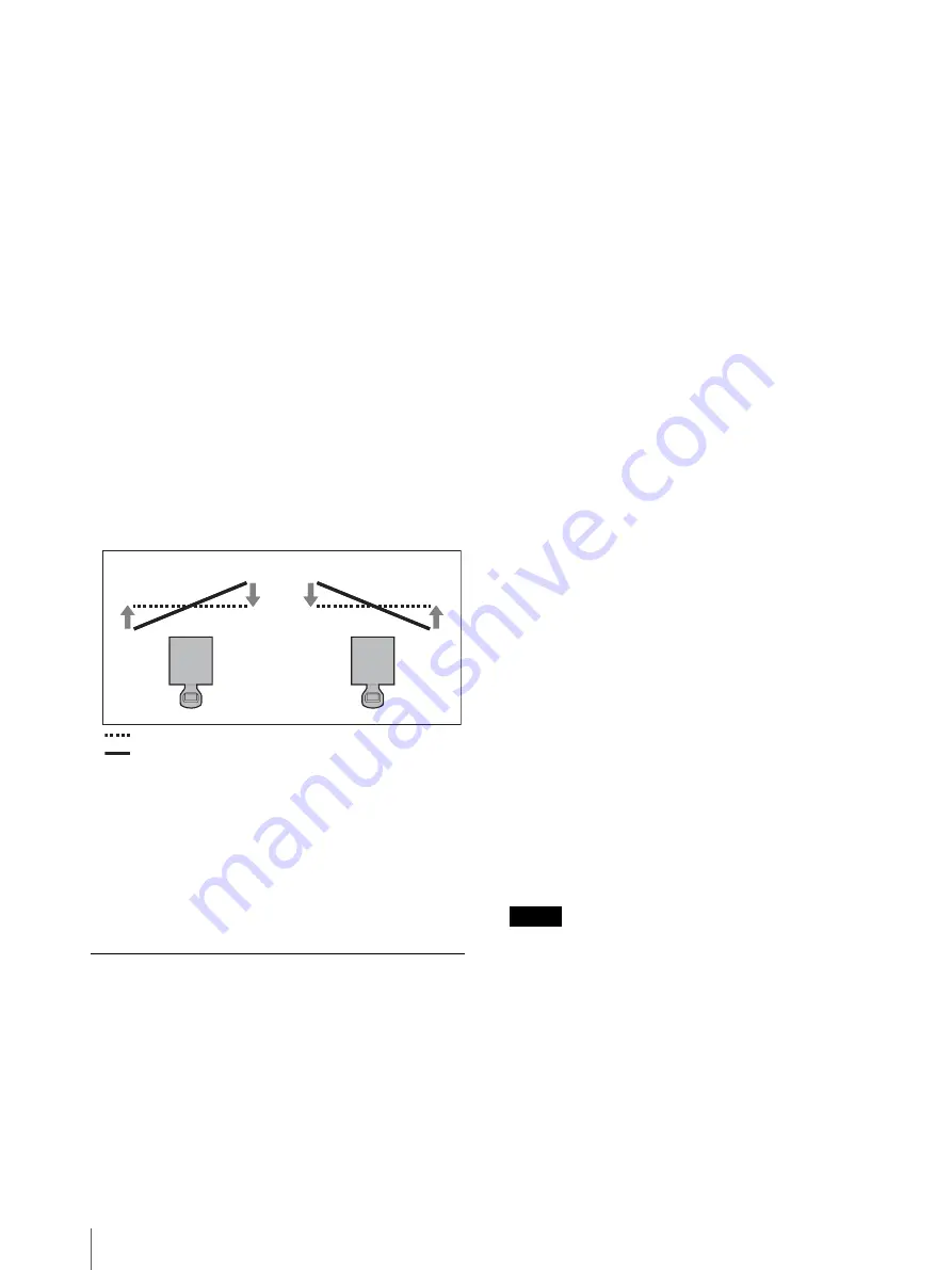
Example of adjustment using the image surface adjustment
screw C (the plus screw on the side of the projection lens)
Turning to the left
Turning to the right
Projected surface (screen)
Image surface


