


7
Caution
When you dispose of the unit or accessories, you must
obey the laws in the relative area or country and the
regulations in the relative hospital.
Warning on power connection
Use a proper power cord for your local power supply.
1. Use the approved Power Cord (3-core mains lead) /
Appliance Connector / Plug with earthing-contacts
that conforms to the safety regulations of each
country if applicable.
2. Use the Power Cord (3-core mains lead) / Appliance
Connector /Plug conforming to the proper ratings
(Voltage, Ampere).
If you have questions on the use of the above Power
Cord/Appliance Connector/Plug, please consult a
qualified service personnel.
Warning on power connection for
medical use
Please use the following power supply cord.
With connectors (plug or female) and cord types other
than those indicated in this table, use the power supply
cord that is approved for use in your area.
*Note: Grounding reliability can only be achieved when the equip-
ment is connected to an equivalent receptacle marked ‘Hospital Only’
or ‘Hospital Grade’.
For the customers in Europe
This product has been manufactured by or on behalf of
Sony Corporation, 1-7-1 Konan Minato-ku Tokyo, 108-
0075 Japan. Inquiries related to product compliance
based on European Union legislation shall be addressed
to the authorized representative, Sony Deutschland
GmbH, Hedelfinger Strasse 61, 70327 Stuttgart,
Germany.
For any service or guarantee matters, please refer to the
addresses provided in the separate service or guarantee
documents.
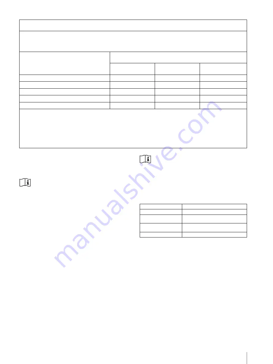
Recommended separation distances between portable and mobile RF communications equipment and the
UP-991AD/UP-971AD
The UP-991AD/UP-971AD is intended for use in an electromagnetic environment in which radiated RF disturbances are
controlled. The customer or the user of the UP-991AD/UP-971AD can help prevent electromagnetic interference by
maintaining a minimum distance between portable and mobile RF communications equipment (Transmitters) and the
UP-991AD/UP-971AD as recommended below, according to the maximum output power of the communications equipment.
Rated maximum output power of transmitter
W
Separation distance according to frequency of transmitter
m
150 kHz to 80 MHz
d
= 1.2
√
P
80 MHz to 800 MHz
d
= 1.2
√
P
800 MHz to 2.5 GHz
d
= 2.3
√
P
0.01
0.12
0.12
0.23
0.1
0.38
0.38
0.73
1
1.2
1.2
2.3
10
3.8
3.8
7.3
100
12
12
23
For transmitters rated a maximum output power not listed above, the recommended separation distance
d
in meters (m) can
be estimated using the equation applicable to the frequency of the transmitter, where
P
is the maximum output power rating
of the transmitter in watts (W) according to the transmitter manufacturer.
NOTE 1: At 80 MHz and 800 MHz, the separation distance for the higher frequency range applies.
NOTE 2: These guidelines may not apply in all situations. Electromagnetic propagation is affected by absorption and
reflection from structures, objects and people.
United States and Canada
Plug Type
HOSPITAL GRADE*
Cord Type
Min.Type SJT
Min.18 AWG
Minimum Rating for Plug
and Appliance Couplers
10A/125V
Safety Approval
UL Listed and CSA
Summary of Contents for UP-971AD
Page 46: ...Sony Corporation ...


