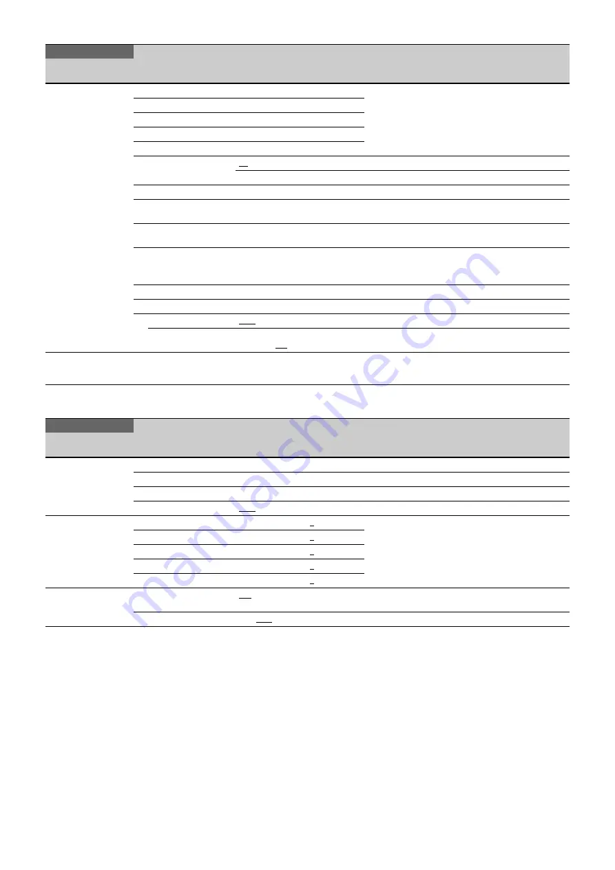
Sony UHC-8300 Operating Instructions Manual Download Page 43

43

MAINTENANCE Menu

<SCENE FILE>
P20

1

Saving and loading a scene file (paint data):

When storing a file in camera memory, specify the 
number after executing STORE.
When reading, only specify the number.

2

3

4

5

STORE

01

 to 32

Specifies a scene file number.

Execute using ENTER.

STANDARD

Execute using ENTER.

Reads the standard paint data.

READ (USB 

t

 CAM)

Execute using ENTER.

Loads 32 scene files from a USB drive to internal 
memory.

WRITE (CAM 

t

 USB)

Execute using ENTER.

Writes 32 scene files in the camera’s memory to a 
USB drive.

FILE ID

Max. 14 characters

Enters a comment for the scene files to be written to a 
USB drive.

See “To specify a character string” (page 21).

CAM CODE

Camera code

Display only

DATE

Date

Display only

DISSOLVE

OFF

, ON

Switches scene files seamlessly.

SPEED

0.2 to 2.8 (0.2 steps), 3 to 10 
(1 steps), 

0.2

MAINTENANCE

Page name
Page No.

Item

Settings

Description

<AUTO SETUP>
M01

AUTO BLACK

Execute using ENTER.

AUTO WHITE

Execute using ENTER.

AUTO LEVEL

Execute using ENTER.

TEST

OFF

, SAW, 10STEP

<WHITE SHADING>
M02

V SAW

R/G/B: –99 to +99, 

0

R, G, and B values can be independently set.

V PARA

R/G/B: –99 to +99, 

0

H SAW

R/G/B: –99 to +99, 

0

H PARA

R/G/B: –99 to +99, 

0

WHITE

R/G/B: –99 to +99, 

0

<OHB MATRIX>
M03

OHB MATRIX

ON

, OFF

Sets hue that is compatible with the HDC2000 HD 
Color Camera.

MATRIX

ON, 

OFF

PAINT

Page name
Page No.

Item

Settings

Description

Summary of Contents for UHC-8300

Page 1: ...8K Color Camera Operating Instructions Before operating the unit please read this manual thoroughly and retain it for future reference UHC 8300 2019 Sony Corporation 5 010 742 11 1 ...

Page 2: ...tting the Electronic Shutter 14 Setting the Focus Assist Functions 14 Setting the Dynamic Focus Function Detail 16 Setting the Gritty Focus Function 16 Loading User Gamma for Viewfinder 17 Setting the Camera Outputs 17 Viewfinder Screen Status Display 18 Menu Operations 20 Starting Menu Operations 20 Selecting Pages 21 Setting Menu Items 21 Editing the USER Menu 22 Menu List 25 Menu Tree 25 OPERAT...

Page 3: ...shown in the figure may have been discontinued For advice on choosing devices please contact your Sony dealer or a Sony sales representative Connection example Note 1 25 inch lens VCT 14 Tripod Attachment Tripod PWS 110NMI IP Live System Manager Station HDVF L770 HDVF L750 Viewfinder a UHC 8300 Optical fiber cable CAC 6 Return Video Selector Intercom headset CAC 12 Microphone Holder Microphone HDV...

Page 4: ...Supports the attachment of a general purpose hand grip i Camera number Insert the supplied camera number label to display the camera number j Shoulder pad You can adjust the position toward the front or rear For details see Adjusting the Shoulder Pad Position page 11 k DC power supply out connector 2 pin Supplies power to an external device up to 2 5 A When supplying power from the DC IN connector...

Page 5: ...t to a position that facilitates operation if its position makes it hard to turn Once you have decided on a position push the lever back into place Do not overtighten the rod lock lever without a rod inserted Always attach and detach the rods two at a time A single rod cannot provide a secure lock j STATUS CANCEL switch STATUS Displays the status information of the unit on the display CANCEL When ...

Page 6: ...mera e RET 2 return video 2 button and select switch When using another system line in parallel with return video 1 use to switch between the video signal of the unit and the return video signal The video signal is displayed on the viewfinder screen The RET 1 button has priority over the RET 2 button if both buttons are pressed If RET 1 and RET 2 buttons are pressed at the same time the two button...

Page 7: ...equipment connected to the AUDIO IN CH1 connector LINE When a line level signal source is connected MIC When an external microphone is connected CH2 channel 2 audio input select switch Set to the appropriate position according to the equipment connected to the AUDIO IN CH2 connector LINE When a line level signal source is connected AES EBU When a digital audio signal is connected The signal must b...

Page 8: ...ing that might have excessive voltage to the following port NETWORK TRUNK connector When you connect the following cable s of the unit to peripheral device use a shielded type cable to prevent malfunction due to radiation noise Network cable Preparations Attaching a Lens For information on handling lenses refer to the lens operation manual Attaching a 1 25 inch lens 1 Turn the lens mount cap count...

Page 9: ...f flange focal length ring lock screw 4 With either manual or power zoom set the zoom ring to telephoto 5 Aim at the flange focal length adjustment chart and turn the focus ring to focus the image 6 Set the zoom ring to wide angle 7 Turn the Ff ring to bring the chart into focus Take care not to move the distance ring 8 Repeat steps 4 to 7 until the image is in focus at both telephoto and wide ang...

Page 10: ...e viewfinder by rotating the front rear positioning lever Detaching the viewfinder Loosen the viewfinder left right positioning ring pull the viewfinder stopper then pull out the viewfinder by sliding it in the direction opposite to that when attached Attaching the Cable Clamp Belt Supplied You can secure the camera cable to the camera by attaching the supplied cable clamp belt 1 Insert the belt b...

Page 11: ...he shoulder pad in the selected position Mounting the Camera to a Tripod Mount the camera to a tripod using a VCT 14 Tripod Attachment Select an appropriate hole from among those at the bottom of the tripod attachment considering the balance of the weight of the camera and the tripod attachment If an inappropriate hole is selected the camera may fall over and may cause injury or damage Check that ...

Page 12: ...and pull the lever in the direction of the arrow If the pin of the tripod attachment does not return to its original position After removing the camera if the pin of the tripod attachment does not return to its original position hold down the red button and move the lever in the direction of the arrow to return the pin to its original position It is not possible to mount a camera with the pin not ...

Page 13: ...uit will work automatically and the viewfinder screen will flicker several times This is not a malfunction If the iris does not close completely change the CC filter to CAP or run Auto Black Balance ABB after attaching the lens cap When automatic black balance adjustment fails If the automatic black balance adjustment process does not end successfully the error message ABB NG will be displayed on ...

Page 14: ...mats the available values are different When shooting at double speed the actual exposure time will be half of the displayed value and the actual frequency will be double the displayed value Selecting the shutter mode and speed Use MSU and RCP to change the shutter speed The current shutter setting will be displayed on the viewfinder screen for about three seconds Example SHUTTER 1 250 Example 59 ...

Page 15: ...8K 7 Turn the MENU SEL knob ENTER button to display the desired setting and press the MENU SEL knob ENTER button 8 To finish the adjustment set the DISPLAY switch to OFF to exit Menu mode Displaying the focus assist indicators The focus assist indicator function extracts the irregularities of a subject and converts the integrated values to a level indicator which shows the focus condition The focu...

Page 16: ...MENU SEL knob ENTER button to align the arrow marker to DYNAMIC FOCUS and press the MENU SEL knob ENTER button The DYNAMIC FOCUS page is displayed 3 Turn the MENU SEL knob ENTER button to align the arrow marker to the item to be set and press the MENU SEL knob ENTER button To use dynamic focus Setting DYNAMIC FOCUS on the VF DETAIL page or this page to ON displays markings of the luminance and col...

Page 17: ...the SDI OUT page Constantly outputting a return video When a camera control unit is connected one of the signals being supplied to the camera control unit can be output from the camera The last selected return signal is output The same textual information as that displayed on the viewfinder screen can be added to the output signal by setting CHARACTER to ON on the SDI OUT page Outputting the same ...

Page 18: ...roximate position of the zoom lens variator between wide angle 0 and telephoto 99 b Lens extender EX is displayed when a lens extender is in use X12 is displayed when a lens with a X1 2 extender is in use c TALK indicator Displayed when the intercom microphone is set to ON d Follow focus indicator Displayed if an offset is superimposed when follow focus is enabled e 5600K mode Displayed when 5600K...

Page 19: ...u press the CANCEL STATUS switch to STATUS The status display is changed to show the following items a Assignable switch indicator The function assigned to the assignable switch page 5 is indicated For the functions that can be assigned see OPERATION menu SWITCH ASSIGN1 16 U09 page 35 b Format indicator The current video format is displayed c display area This area is used to display abnormal stat...

Page 20: ...E menu This menu allows you to edit the USER menu For details see Editing the USER Menu page 22 ALL menu This menu permits you to control all items of the OPERATION menu PAINT menu MAINTENANCE menu FILE menu and DIAGNOSIS menu as a single menu OPERATION menu This menu contains items for camera operators to operate the camera It mainly permits viewfinder intercom and switch settings PAINT menu This...

Page 21: ... ENTER button the setting will be returned to its previous value To interrupt settings Set the DISPLAY switch to OFF to turn off the menu screen display The setting operation can be restarted by setting the DISPLAY switch back to MENU 4 Press the MENU SEL knob ENTER button The mark changes back to the arrow marker and the new setting will be registered 5 To change other setting items on the same m...

Page 22: ...ed items to the page While the EDIT page contains factory preset items the USER 1 EDIT to USER 19 EDIT pages are all blank in their initial state You can register up to 10 items including blank lines on each of these pages To add items to a page Proceed as follows 1 Set the DISPLAY switch from OFF to MENU while holding the MENU SEL knob ENTER button pressed The TOP MENU screen appears 2 Turn the M...

Page 23: ... you selected in step 3 In the above example ASSIGNABLE is moved to the top and the other items are moved down one line To insert a blank line Proceed as follows 1 Turn the MENU SEL knob ENTER button to move the arrow marker to the item above which you wish to insert a blank line The EDIT FUNCTION screen appears 2 Select BLANK then press the MENU SEL knob ENTER button The previously displayed page...

Page 24: ...ES NO appears at the upper right 3 To delete turn the MENU SEL knob ENTER button to move the arrow marker to YES and press the MENU SEL knob ENTER button To move a page Proceed as follows 1 Display the EDIT PAGE screen of the USER MENU CUSTOMIZE menu Turn the MENU SEL knob ENTER button to move the arrow marker to the page that you wish to move The EDIT FUNCTION screen appears 2 Select MOVE then pr...

Page 25: ...METER1 06 FOCUS POSITION METER CURRENT FOCUS DIST FOCUS POSITION METER2 07 ADJUSTED SIGN MARKER CONFIG CURRENT FOCUS DIST ZOOM LINK CRISP LEVEL PEAK COLOR THRESHOLD COLOR LEVEL AREA VF DETAIL COLOR DE RETURN DISABLE DYNAMIC FOCUS TAIL FOCUS ASSIST 08 U03 RET MIX VF MIX DIRECTION MIX VF MODE MIX VF LEVEL CHARACTER LEVEL ZEBRA 10 U08 ZEBRA ZEBRA1 ZEBRA2 SWITCH ASSIGN1 16 U09 ASSIGNABLE REAR ASSIGN1 ...

Page 26: ...LK GAM KNEE WHT CLIP DETAIL LVL DEP SKIN DTL MATRIX WHITE BLACK FLARE GAMMA FLARE V MOD TEST WHITE ATW COLOR TEMP BALANCE MASTER LEVEL COARSE TABLE GAMMA TEST LEVEL RANGE TEST SATURATION LOW KEY SAT RANGE TEST K POINT K SLOPE KNEE KNEE MAX KNEE SAT W CLIP ABS DETAIL LEVEL LIMITER M LIMITER WHT LIMITER BLK CRISP LEVEL DEPEND ABS DETAIL 2 P10 H V R HD DETAIL DETAIL P11 LEVEL LIMITER M LIMITER WHT LI...

Page 27: ...DR WHITE CLIP HDR BLACK CLIP HDR BLACK COMPRESSION SCENE FILE P20 1 2 3 4 5 STORE STANDARD READ USB t CAM WRITE CAM t USB FILE ID CAM CODE DATE DISSOLVE AUTO SETUP M01 WHITE SHADING M02 OHB MATRIX M03 AUTO IRIS M04 LENS1 M05 MIC GAIN M07 CALL TALLY M08 SYSTEM FORMAT M09 U12 AUTO BLACK AUTO WHITE AUTO LEVEL TEST V SAW V PARA H SAW H PARA WHITE OHB MATRIX MATRIX AUTO IRIS WINDOW OVERRIDE IRIS LEVEL ...

Page 28: ...CAM WRITE CAM t USB FILE ID CAM CODE DATE READ USB t CAM PRESET FILE ID CAM CODE DATE STORE FILE No NAME F NO CENTER MARKER STORE FILE PRESET OPER BOX CURSOR FILE F08 1 2 3 4 5 STORE READ USB t CAM WRITE CAM t USB ATOR REFERENCE ALL OHB WHITE SHADE ALL OHB BLACK SHADE OHB ND OFFSET MATRIX FILE F07 CUSTOM PRESET MATRIX CAM INPUT VOLTAGE CAM CONSUMPTION OPTICAL LEVEL D01 BOARD STATUS D02 ROM VERSION...

Page 29: ...RMAL Displayed in the range 0 to 255 no units NORMAL When a parallel lens is attached cannot be changed ABS AUTO Displayed in the units meters or feet set on the lens ABS m Displayed in meters ABS ft Displayed in feet The NORMAL setting cannot be used when a Cooke lens is attached The default setting is ABS AUTO IND 02 U05 ND ON OFF 1 2 3 4 combination allowed IND Turns the display area page 19 on...

Page 30: ... Sets the darken level outside the aspect area SAFETY ON OFF OFF AREA Sets the safety marker in Aspect mode OFF AREA Displayed when AREA MARKER of FOCUS ASSIST is ON 80 0 90 0 92 5 95 0 VF DETAIL 04 U02 VF DETAIL ON OFF 0 to 100 25 CRISP 99 to 99 0 FREQUENCY 9M 14M 18M FLICKER ON OFF AREA 100 70 60 50 40 30 20 10 H 99 to 99 0 V 99 to 99 0 ZOOM LINK ON OFF 0 25 50 75 100 COLOR DETAIL ON OFF BLUE RE...

Page 31: ...COLOR indicator AREA 100 70 60 50 40 30 20 10 H 99 to 99 0 V 99 to 99 0 FOCUS POSITION METER1 06 FOCUS POSITION METER OFF ON Shows hides the focus position meter NEAR LIMIT 0 to 999 Sets the NEAR edge of the focus position meter FAR LIMIT 0 to 999 Sets the FAR edge of the focus position meter DIRECTION HORIZONTAL VERTICAL Sets the display direction of the focus position meter HORIZONTAL Horizontal...

Page 32: ... YELLOW ORANGE PURPLE GRAY BLACK WHITE Sets the color of triangular parts of the marker Cannot be registered here if marker registration has been assigned to a dedicated switch NAME MKR1 2 3 Max 8 characters Default value MARKER 1 to 3 Sets the text of the marker name See To specify a character string page 21 POS MKR1 2 3 0 to 999 Sets the position of the marker CURRENT FOCUS DIST Displays the cur...

Page 33: ... 30 10 ZEBRA2 50 to 109 100 CURSOR 11 U07 CURSOR ON OFF LEVEL WHITE BLACK DOT 0 to 100 40 BOX CROSS BOX CROSS H POSITION 0 to 99 50 V POSITION 0 to 99 50 WIDTH 0 to 99 50 HEIGHT 0 to 99 50 BOX MEMORY 1 2 3 OFF ON H POSI 1 2 3 0 to 99 50 V POSI 1 2 3 0 to 99 50 WIDTH 1 2 3 0 to 99 50 HEIGHT 1 2 3 0 to 99 50 BOX CURSOR FILE 12 1 BOX CURSOR FILE selection FILE name input Align the cursor to the left ...

Page 34: ...LE Execute using ENTER Designates the current angle as level 0 CLEAR Execute using ENTER Sets OFFSET to 0 VF OUT 14 U01 VF OUT COLOR Y R G B RET MIX VF ON OFF MIX DIRECTION MAIN RET MIX VF MODE Y MIX Y C MIX WIRE W WIRE B MIX VF LEVEL 0 to 99 CHARACTER LEVEL 0 to 5 4 PinP OFF RETURN HD PROMPTER POSITION 1 2 3 4 SIZE 1 2 5 1 3 1 4 MODE PinP OFF PinP RETURN 1 2 3 4 PinP HD PROMPTER 1 2 Main picture ...

Page 35: ... SW INCOM1 INCOM2 VF DETAIL MIX VF 5600K FAN MAX VF ASSIGN SW1 VF ASSIGN SW2 SPIRIT LEVEL INDICATOR FOCUS ASSIST INDICATOR PinP RET1 SW TOGGLE RET2 SW TOGGLE RET3 SW TOGGLE CURSOR ALL OFF FLAG DYNAMIC FOCUS AWB REAR ASSIGN1 OFF RETURN1 SW RETURN2 SW RETURN3 SW RETURN4 SW INCOM 1 INCOM 2 EXTENDER 5600K VF DETAIL SPRIT LEVEL INDICATOR FOCUS ASSIST INDICATOR PinP VF ASSIGN SW1 VF ASSIGN SW2 FOCUS POS...

Page 36: ...SW INCOM 1 INCOM 2 EXTENDER 5600K VF DETAIL SPIRIT LEVEL FOCUS ASSIST PinP VF ASSIGN SW1 VF ASSIGN SW2 MAG USER1 MAG USER2 MAG USER3 MAG USER1 TOGGLE MAG USER2 TOGGLE MAG USER3 TOGGLE RET3 Pin4 OFF RETURN1 SW RETURN2 SW RETURN3 SW INCOM 1 INCOM 2 EXTENDER 5600K VF DETAIL SPIRIT LEVEL FOCUS ASSIST PinP VF ASSIGN SW1 VF ASSIGN SW2 MAG USER1 MAG USER2 MAG USER3 MAG USER1 TOGGLE MAG USER2 TOGGLE MAG U...

Page 37: ...WER ON OFF ON OFF Settings in With DYNAMIC or CARBON cannot be changed UNBAL ON OFF ON OFF Settings in With CARBON cannot be changed INTERCOM1 21 INTERCOM1 RECEIVE SELECT SEPARATE MIX INTERCOM LEFT RIGHT BOTH When ENG PROD is set to MIX this item is split into ENG and PROD items with same settings PGM1 LEFT RIGHT BOTH PGM2 LEFT RIGHT BOTH TRACKER LEFT RIGHT BOTH SIDE TONE MU 1 to 99 50 INTERCOM1 2...

Page 38: ...file to be written to a USB drive See To specify a character string page 21 CAM CODE Camera code Display only DATE Date Display only PAINT Page name Page No Item Settings Description SW STATUS P01 FLARE ON OFF GAMMA ON OFF BLK GAM ON OFF KNEE ON OFF WHT CLIP ON OFF DETAIL ON OFF LVL DEP ON OFF SKIN DTL ON OFF MATRIX ON OFF VIDEO LEVEL P02 WHITE R G B 99 to 99 0 R G B and M master values can be ind...

Page 39: ...9 to 99 0 ON OFF LOW KEY SAT 99 to 99 0 RANGE LOW L MID H MID HIGH ON OFF TEST OFF SAW 10STEP KNEE P07 K POINT R G B M 99 to 99 0 R G B and M master values can be independently set Absolute values are displayed in ABS mode except for M master K SLOPE R G B M 99 to 99 0 KNEE ON OFF KNEE MAX ON OFF KNEE SAT 99 to 99 0 ON OFF WHITE CLIP P08 W CLIP 99 to 99 0 ON OFF ABS Highlighted ABS Absolute mode D...

Page 40: ...ue is displayed in ABS mode LIMITER M 99 to 99 0 LIMITER WHT 99 to 99 0 Absolute value is displayed in ABS mode LIMITER BLK 99 to 99 0 Absolute value is displayed in ABS mode CRISP 99 to 99 0 Absolute value is displayed in ABS mode LEVEL DEPEND 99 to 99 0 Absolute value is displayed in ABS mode ON OFF H V RATIO 99 to 99 0 Absolute value is displayed in ABS mode FREQ 99 to 99 0 Absolute value is di...

Page 41: ...9 to 99 0 G R 99 to 99 0 G B 99 to 99 0 B R 99 to 99 0 B G 99 to 99 0 MATRIX ON OFF PRESET ON OFF SMPTE 240M ITU 709 SMPTE WIDE NTSC EBU ITU 601 CUSTOM1 CUSTOM2 CUSTOM3 CUSTOM4 CUSTOM5 USER ON OFF MULTI ON OFF ADAPTIVE MATRIX OFF ON LEVEL 0 to 7 0 MULTI MATRIX P16 PHASE 0 23 45 68 90 113 135 158 180 203 225 248 270 293 315 338 Selects an axis angle at PHASE for which the multimatrix adjustment is ...

Page 42: ...FFSET 30 to 30 0 0 Enabled only when LIVE HDR is selected HDR output black offset HDR KNEE OFF ON Enabled only when LIVE HDR is selected KNEE setting applied for HDR POINT 99 to 99 0 SLOPE 99 to 99 0 HDR WHITE CLIP OFF ON Enabled only when LIVE HDR is selected LEVEL 99 to 99 0 HDR BLACK CLIP OFF ON HDR BLACK COMPRESSION OFF ON LIVE TONE CONTROL P19 LIVE TONE CONTROL ON OFF Turns the live tone cont...

Page 43: ...or the scene files to be written to a USB drive See To specify a character string page 21 CAM CODE Camera code Display only DATE Date Display only DISSOLVE OFF ON Switches scene files seamlessly SPEED 0 2 to 2 8 0 2 steps 3 to 10 1 steps 0 2 MAINTENANCE Page name Page No Item Settings Description AUTO SETUP M01 AUTO BLACK Execute using ENTER AUTO WHITE Execute using ENTER AUTO LEVEL Execute using ...

Page 44: ...from the lens is always displayed AF DISPLAY ON OFF OFF EFFECT OFF ASSIST IND OFF EFFECT Displayed when EFFECT of VF MARKER is ON OFF ASSIST IND Displayed when INDICATOR of FOCUS ASSIST is ON ALAC AUTO OFF With AUTO selected the status is displayed at the right ACTIVE Compensation is in progress WAIT Waiting for completion of lens initialization STOP Compensation is turned off for a non applicable...

Page 45: ...BER to the same number as the CCU number TALLY GUARD Selects whether to prevent changes while TALLY is lit EXTENDER OFF ON FILTER DISC OFF ON SYSTEM FORMAT M09 U12 CURRENT Displays the current format display only SYNC OUT M10 U13 OUTPUT SD SYNC HD SYNC V PHASE 999 to 999 0 H PHASE 999 to 999 0 SDI OUT M11 U14 SDI 1 OUT OFF MAIN LINK A 3G SDI HD PROMPTER 4K VF 4K PROMPTER SDI 2 OUT IN OFF MAIN LINK...

Page 46: ...2 3 4 5 STORE 01 to 32 Specifies a scene file number Execute using ENTER STANDARD Execute using ENTER Reads the standard paint data READ USB t CAM Execute using ENTER Loads 32 scene files from a USB drive to internal memory WRITE CAM t USB Execute using ENTER Writes 32 scene files in the camera s memory to a USB drive FILE ID Max 14 characters Enters a comment for the scene files to be written to ...

Page 47: ...nce stored the values do not need to be stored again if the sensor is reinstalled MATRIX FILE F07 CUSTOM PRESET MATRIX Stores matrix preset files Saved files can be loaded by setting PRESET of USER MATRIX to CUSTOM 1 to 5 STORE FILE 1 Execute using ENTER 2 Execute using ENTER 3 Execute using ENTER 4 Execute using ENTER 5 Execute using ENTER CLEAR ALL Execute using ENTER Clears all the files READ U...

Page 48: ...EN YELLOW RED NG NO SIGNAL Displayed only when a CCU is connected CAM t CCU GREEN YELLOW RED NG NO SIGNAL Displayed only when a CCU is connected BOARD STATUS D02 OHB OK NG DPR OK NG SY OK NG PS OK NG TX OK NG HOURS METER xxxx H Displays the total working time ROM VERSION D03 U15 CAMERA APP Vx xx OS Vx xx SY Vx xx DPR Vx xx TX Vx xx PS Vx xx SERIAL NO D04 MODEL UHC 8300 NO xxxxxxx POWER SUPPLY STAT...

Page 49: ...n displayed when an UHCU 8300 unit is not connected is used to confirm menu settings The PAINT adjustment functions are not available Camera CMOS image sensor phenomena The following phenomena that may occur in images are specific to image sensors They do not indicate a malfunction White flecks Although the image sensors are produced with high precision technologies fine white flecks may be genera...

Page 50: ...rly SET SYSTEM CLOCK The time date of the internal clock have not been set OHB BLOCK NG A problem was detected in the optical block MSU RPN BUSY RPN compensation was attempted using the camera menu while being operated from an external device Consult Sony service personnel VF RPN BUSY RPN compensation was attempted from an external device while being operated using the camera menu Consult Sony ser...

Page 51: ...operations balanced When AUDIO switch is set to LINE 0 dBu balanced INTERCOM 1 INTERCOM 2 XLR type 1 each EARPHONE Stereo mini jack 1 DC IN XLR 4 pin 1 10 5 V to 17 V DC DC OUT 4 pin 1 DC 10 5 V to 17 V max 0 5 A This may be limited by the imposed load or inputs 2 pin 1 DC 10 5 V to 17 V max 2 5 A This may be limited by the imposed load or inputs When supplying power from the DC IN connector power...

Page 52: ...rly before use SONY WILL NOT BE LIABLE FOR DAMAGES OF ANY KIND INCLUDING BUT NOT LIMITED TO COMPENSATION OR REIMBURSEMENT ON ACCOUNT OF THE LOSS OF PRESENT OR PROSPECTIVE PROFITS DUE TO FAILURE OF THIS UNIT EITHER DURING THE WARRANTY PERIOD OR AFTER EXPIRATION OF THE WARRANTY OR FOR ANY OTHER REASON WHATSOEVER SONY WILL NOT BE LIABLE FOR CLAIMS OF ANY KIND MADE BY USERS OF THIS UNIT OR MADE BY THI...

Reviews: