– 7 –
SECTION 4
ADJUSTMENTS
4-1. MECHANICAL ADJUSTMENTS
PRECAUTION
1. Clean the following parts with a denatured-alcohol-moistened
swab :
record/playback head pinch roller
erase head
rubber belts
capstan
2. Demagnetize the record/playback head with a head demagne-
tizer.
3. Do not use a magnetized screwdriver for the adjustments.
4. After the adjustments, apply suitable locking compound to the
parts adjusted.
5. The adjustments should be performed with the rated power sup-
ply voltage unless otherwise noted.
r
Torque Measurement
Mode
Torque Meter
Meter Reading
Forward
CQ-102C
30 to 65 g•cm
(0.42 – 0.9 oz•inch)
Forward
CQ-102C
1 to 7 g•cm
Back Tension
(0.0134– 0.097 oz•inch)
Reverse
CQ-102RC
30 to 65 g•cm
(0.41 – 0.9 oz•inch)
Reverse
CQ-102RC
1 to 7 g•cm
Back Tension
(0.0134– 0.097 oz•inch)
FF, REW
CQ-201B
70 to 120 g•cm
(0.972– 1.66 oz•inch)
4-2. ELECTRICAL ADJUSTMENTS
1. The adjustment should be performed in the publication.
(Be sure to make playback adjustment at first.)
2. The adjustment and measurement should be performed for
both L-CH and R-CH.
r
Switch position
DOLBY NR switch
: OFF
DIR MODE switch
:
A
r
Standard record position :
Deliver the standard input signal level to input jack and set
the REC LEVEL control to obtain the standard output signal
level as follows.
Record Mode
set
TAPE OUT
+
–
TAPE IN
AF OSC
attenuator
600
Ω
10 k
Ω
47 k
Ω
level meter
r
Standard Input Level
Input Terminal
TAPE IN
source impedance
10k
Ω
input signal level
0.5V (–3.8dB)
r
Standard Output Level
Output Terminal
TAPE OUT
load impedance
47k
Ω
output signal level
0.5V (–3.8dB)
r
Test tape
Tape
Contents
Use
P-4-A100
10 kHz,
–10dB
Azimuth Adjustment
P-4-L300
315Hz,
0dB
PB Level Adjustment
WS-48B
3kHz,
0dB
Tape Speed Adjustment
0dB=0.775V
TC Test Mode
setting :
Push POWER button with STOP key and REC MUTE
key.
function :
r
when start recording, COUNTER is set to “0000”
and COUNTER MEMORY function is effective
(“MEMORY” appears on FLD).
r
While playing or AMS, the signal level is displayed.
(“L” / “H”)
r
Test tape
Tape
Contents
Use
P-4-A100
10 kHz,
–10dB
Head Azimuth Adjustment
P-4-L300
315Hz,
0dB
Level Adjustment
WS-48B
3kHz,
0dB
Tape Speed Adjustment
0dB=0.775V
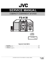
Record/Playback Head Azimuth Adjustment
r
Carrey out servicing or repairs form the REVERSE direction
first.
Procedure :
1. Mode : Forward playback
set
level meter
+
–
test tape
P-4A100
(10kHz, –10dB)
47 k
Ω
TAPE OUT
2. Turn the adjustment screw for the maximum output levels. If
these levels do not match, turn the adjustment screw until both
of output levels match together within 1dB.
L-CH
peak
R-CH
peak
L-CH
peak
R-CH
peak
Screw
position
output
level
within
1 dB
within
1 dB
screw angle