background image

– 19 –

KV-T25SZ8

RM-870

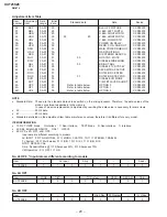
Adjustment Item Table

Data
range

Initial

data

Standard data

Note

Device

Item

Adjustment

number

Item

00

HSF

00–3F

24

50: 1F

60: 1F

H SHIFT

TDA8375

01

HSZ

00–3F

23

50: 1F

60: 1F

H SIZE

TDA8375

02

PAP

00–3F

21

50: 2E

60: 2D

PIN AMPLITUDE

TDA8375

03

CNP

00–3F

29

50: 23

60: 26

CORNER PIN

TDA8375

04

TLT

00–3F

20

50: 21

60: 25

TILT

TDA8375

05

VSL

00–3F

20

50: 20

60: 20

V SLOPE

TDA8375

06

VAP

00–3F

1D

50: 38

60: 34

V AMPLITUDE

TDA8375

07

SCR

00–3F

20

50: 20

60: 20

S CORRECTION

TDA8375

08

VSF

00–3F

20

50: 2A

60: 2B

V SHIFT

TDA8375

09

RDR

00–3F

25

26

WHITE POINT R

TDA8375

0A

GDR

00–3F

20

WHITE POINT G

TDA8375

0B

BDR

00–3F

20

WHITE POINT B

TDA8375

0C

FO

00–02

00

TV: 00

VIDEO: 00

TEXT: 01 PHI-1 TIME CONSTANT

TDA8375

0D

AGC

00–3F

30

TV: 2A

VIDEO: 2A

TEXT: 2A AGC TAKE OVER

TDA8375

0E

VSW

00–01

00

TV: 00

VIDEO: 01

TEXT: 00 VIDEO MUTE

TDA8375

0F

FOR

00–03

00

03

FORCED FIELD FREQ.

TDA8375

10

DL

00–01

00

INTERLACE

TDA8375

11

POC

00–01

00

SYNCHRO MODE FIX

TDA8375

12

VID

00–01

00

VIDEO IDENT MODE

TDA8375

13

HCO

00–01

00

EHT TRACKING MODE

TDA8375

14

EVG

00–01

00

ENABLE V GUARD

TDA8375

15

SBL

00–01

00

SERVICE BLANKING

TDA8375

16

PRD

00–01

00

OVER-VOLTAGE INPUT

TDA8375

17

COR

00–01

00

NOISE CORING PEAK

TDA8375

18

PMX

00–3F

27

Others:

Normal: 2C

PICTURE MAX DATA

TDA8375

19

PMI

00-3F

05

Others:

Normal: 04

PICTURE MIN DATA

TDA8375

1A

SBR

00–7F

4B

Others:

Normal: 54

SUB-BRIGHTNESS

TDA8375

1B

SHU

00–0F

07

SUB-HUE

TDA8375

1C

SSH

00–03

01

TV: 01

VIDEO: 02

SUB-SHARPNESS

TDA8375

1D

SC1

00–3F

1F

 50: 26

60: 29

SUB-COLOR LOWER

TDA8375

1E

SC2

00–3F

0B

 50: 0C

60: 0F

SUB-COLOR HIGHER

TDA8375

1F

AIP

00–7F

3F

ADJUSTMENT IF PLL

TDA8375

20

VZM

00–3F

19

VERTICAL ZOOM

TDA8375

21

FAW

00–FF

08

NICAM FAW THRESH

MSP3410

22

CTM

00–FF

08

NICAM ERROR BIT (MONO)

MSP3410

23

CTN

00–FF

50

NICAM ERROR BIT (NICAM)

MSP3410

24

WCD

00–FF

0A

W. G. CHANGE DATA

MSP3410

25

WST

00–FF

15

W. G. STEREO CUT POINT

MSP3410

26

WTM

00–FF

50

W. G. TIMER CHANGE

MSP3410

27

WBT

00–FF

EA

W. G. BILINGUAL

MSP3410

28

ACG

00–01

01

AGC AUTO/CONST.

MSP3410

29

CDB

00–3F

28

AGC GAIN CONST.

MSP3410

2A

FGP

00–7F

24

FM (BG, I, DK) PRESCALE

MSP3410

2B

FMP

00–7F

40

FM (M) PRESCALE

MSP3410

2C

WGP

00–7F

3C

W. G. PRESCALE

MSP3410

2D

NIP

00–7F

7F

NICAM PLESCALE

MSP3410

2E

CRM

00–01

00

CARRIOR MUTE

MSP3410

2F

CMI

00–03

00

CARRIOR MUTE LEVEL

MSP3410

30

ACO

00–01

01

AUDIO CLOCK OUT

MSP3410

31

WAC

00–0F

01

W. G. AGREEMENT COUNT

MSP3410

32

DLY

00–FF

30

STEREO SEARCH DELAY

MSP3410

33

DLG

00–FF

10

W/G SEARCH DELAY

MSP3410

34

TXP

00–0F

09

0D

TEXT PICTURE CONT.

SAA5281

35

MXP

00–0F

0D

0F

TEXT MIX MODE PIC.

SAA5281

Summary of Contents for TRINITRON KV-T25SZ8

Page 1: ...MODEL COMMANDER DEST CHASSIS NO KV T25SZ8 RM 870 Australia SCC J99F A SERVICE MANUAL MODEL COMMANDER DEST CHASSIS NO TRINITRON COLOR TV BG 1S CHASSIS ...

Page 2: ...o jacks Video 1 Vp p 75 ohms Audio 500 mVrms Picture tube 25 in Tube size cm 64 Measured diagonally Screen size cm 60 Measured diagonally Dimensions w h d mm 613 542 472 Mass kg 32 Design and specifications are subject to change without notice CAUTION SHORT CIRCUIT THE ANODE OF THE PICTURE TUBE AND THE ANODE CAP TO THE METAL CHASSIS CRT SHIELD OR CARBON PAINTED ON THE CRT AFTER REMOVING THE ANODE ...

Page 3: ...d White Balance Adjustments 15 4 SELF DIAGNOSIS FUNCTION 16 5 CIRCUIT ADJUSTMENTS 5 1 Adjustments with Commander 17 5 2 Adjustment Method 18 5 3 A Board Adjustment after IC003 Memory Replacement 21 5 4 Picture Distortion Adjustment 21 6 DIAGRAMS 6 1 Block Diagram 23 6 2 Circuit Boards Location 27 6 3 Schematic Diagrams and Printed Wiring Boards 27 1 Schematic Diagram of A Board 31 2 Schematic Diag...

Page 4: ...ECTION 1 GENERAL The operating instructions mentioned here are partial abstracts from the Operating Instructions Manual The page numbers of the Operating Instruction Manual remain as in this manual 2 3 AUTO PROGR AUTO PROGR ...

Page 5: ... the black plug to AUDIO L MONO Getting Started 5 Front of TV EN When using the video input jacks Do not connect video equipment to the video input jacks at the front and the rear of your TV simultaneously otherwise the picture will not be displayed properly on the screen to video and audio outputs to antenna socket MONITOR OUT Rear of TV to antenna output to video and audio inputs Signal flow or ...

Page 6: ...ting channels automatically You can preset up to 80 TV channels in numerical sequence from program position 1 Front of TV Note TV SYSTEM button is not used for this model 1 Press POWER When the TV is in standby mode after pressing POWER press POWER on the remote commander 2 Press AUTO PROGR To start presetting channels automatically from the specified program position 1 Press MANUAL PROGR 2 Press ...

Page 7: ...tting the Sleep Timer You can set the TV to turn off automatically after the period of time you want Press SLEEP To cancel the Sleep Timer press SLEEP repeatedly until SLEEP TIMER OFF appears or turn the TV off Changing the on screen display language If you prefer Chinese to English you can change the on screen display language You can use buttons on the remote commander or the TV 1 Press SELECT u...

Page 8: ...UME Press MUTING Press A B ENLARGE No color Adjust the COLOR level in the on screen display Check the COLOR SYSTEM setting TV cabinet creaks Even if the picture or the sound is normal changes in the room temperature sometimes make the TV cabinet expand or contract making a noise This does not indicate a malfunction Note on the remote commander The supplied remote commander is used on several model...

Page 9: ... 870 2 1 REAR COVER REMOVAL 2 3 F1 BOARD REMOVAL SECTION 2 DISASSEMBLY 2 2 A BOARD REMOVAL 2 4 SERVICE POSITION 2 Two screws BVTP 4 16 3 One screw BVTP 3 16 1 Two screws BVTP 4 16 Lever Lever A board F1 board A board ...

Page 10: ...change with the new parts and fix them with screws BVTP respectively 2 5 1 REPLACEMENT OF MULTI BUTTON 2 5 2 REPLACEMENT OF POWER BUTTON AND LIGHT GUIDE 2 6 DEMAGNETIZATION COIL REMOVAL Two screws BVTP 3 12 Two screws BVTP 3 12 Cut Light guide Power button 3 Demagnetization coil 4 Tension spring Picture tube 2 DGC holder 1 DGC band Remove the claw ...

Page 11: ...bber too hard so as not to damage the inside of anode caps A metal fitting called the shatter hook terminal is built into the rubber 3 Do not turn the foot of rubber over too hard The shatter hook terminal will stick out or damage the rubber REMOVAL OF ANODE CAP NOTE After removing the anode short circuit the anode of the picture tube and the anode cap to the metal chassis CRT shield or carbon pai...

Page 12: ...a d a c b d a b c d Fig 3 1 Neck assy G1 G2 G3 Preparation In order to reduce the influence of geomagnetism on the set s picture tube face it east or west Switch on the power and degauss with the degausser 3 1 BEAM LANDING 1 Input a white signal with the pattern generator Contrast Brightness 2 Position neck assy as shown in Figure 3 1 3 Set the pattern generator raster signal to a green raster 4 M...

Page 13: ...VR magnet so that the red green and blue dots converge on top of each other in the center of the screen The respective dot positions resulting from moving each magnet interact so be sure to perform adjustment while tracking Use the V STAT magnet to adjust the red green and blue dots so they coincide at the center of screen by moving the dots in the horizontal direction BMC Hexapole V STAT Purity O...

Page 14: ...ion Before starting this adjustment adjust the horizontal static convergence and the vertical static convergence 1 Slightly loosen the deflection yoke screws 2 Remove the deflection yoke spacer R G B R G B R G B R G B R G B R G B R G B R G B R G B R G B R G B R G B 3 Screen corner Convergence a d screen corner misconvergence b a c d Fix a Permalloy assy corresponding to the misconverged areas Perm...

Page 15: ...e adjusted items again to confirm adjustments were made Item number Note Adjustment item Initial DATA 09 RDR 25 WHITE POINT R 0A GDR 20 WHITE POINT G 0B BDR 20 WHITE POINT B SERVICE MUTING 1 F DATA RDR Adjustment Item 09 Item number WRITE 1 F RDR 09 0 Executes the writing 3 4 G2 SCREEN AND WHITE BALANCE ADJUSTMENTS 1 G2 SCREEN ADJUSTMENT RV701 1 Set the PICTURE and BRIGHTNESS to normal 2 Put to VI...

Page 16: ...imes Flickering is operated by lighting the LED s for 60ss each time The flickering frequency responding to each failed device is shown below All the devices are checked one after another from the left of the table If an error is found the responding LED will start flickering So if more than 1 device have failed only the one on the left side will flicker Device Flickering Frequency NONVOLATILE MEM...

Page 17: ...g 7 0 All the data becomes the values in memory 8 0 All user control goes to the standard state 5 0 Service data initialization Be sure not to use usually 2 0 Write 50Hz adjustment data to 60Hz or vice versa The screen display is 1 4 Select the adjustment item 3 6 Raise lower the data MUTING Writes 0 Executes the writing MUTING TEXT VIDEO HOLD TV TEXT CLR SELECT PIC MODE A B ENLARGE WAKE UP INDEX ...

Page 18: ...th the MUTING button 5 Execute the writing with the 0 button The WRITE display will be changed to green SERVICE Use the same method for Items Number 00 4B Use 1 and 4 to select the adjustment item use 3 and 6 to adjust write with MUTING then execute the write with 0 WRITE WRITE GREEN 0C VSF 08 SERVICE 50 50 50 GREEN 0C VSF 08 Adjust with the 3 and 6 buttons Written with the MUTING Write executed w...

Page 19: ...75 17 COR 00 01 00 NOISE CORING PEAK TDA8375 18 PMX 00 3F 27 Others Normal 2C PICTURE MAX DATA TDA8375 19 PMI 00 3F 05 Others Normal 04 PICTURE MIN DATA TDA8375 1A SBR 00 7F 4B Others Normal 54 SUB BRIGHTNESS TDA8375 1B SHU 00 0F 07 SUB HUE TDA8375 1C SSH 00 03 01 TV 01 VIDEO 02 SUB SHARPNESS TDA8375 1D SC1 00 3F 1F 50 26 60 29 SUB COLOR LOWER TDA8375 1E SC2 00 3F 0B 50 0C 60 0F SUB COLOR HIGHER T...

Page 20: ... CXP85200 4A OP1 00 FF 07 Refer to table below OPTION 1 CXP85200 4B OP2 00 FF 00 Refer to table below OPTION 2 CXP85200 NOTE Standard Data Those are the standard data values written on the microprocessor Therefore the data values of the modes are stored respectively in the memory In case of a device replacement adjustment by rewriting the data value is necessary for some items 50 50 Hz data 60 60 ...

Page 21: ...IC003 MEMORY REPLACEMENT 1 Enter to Service Mode 2 Press commander buttons 5 and 0 Data Initialize and 2 and 0 Data Copy to initialize the data 3 Call each item number and check if the respective screen shows the normal picture In case some items are not well adjusted give them fine adjustment Write the data per each item number MUTING 0 4 Select item numbers 49 OP0 4A OP1 and 4B OP2 and respectiv...

Page 22: ... 22 KV T25SZ8 RM 870 MEMO ...

Page 23: ...SCREW STEP TAPPING 15 4 046 765 21 SCREW TAPPING 16 8 733 255 01 PICTUTE TUBE M60KWL70X 17 8 451 404 41 DEFLECTION YOKE Y25GXAS 18 1 452 762 31 NECK ASSEMBLY NA294 19 A 1342 396 A VM BOARD COMPLETE 20 A 1331 743 A C BOARD COMPLETE 21 4 046 600 11 SPACER DY 22 3 704 372 11 HOLDER HV CABLE 23 4 369 318 61 SPRING TENSION 24 1 403 619 11 COIL DEMAGNETIZATION 25 4 043 827 13 BAND DEGAUSSING COIL 26 4 0...

Page 24: ...10 50V C036 1 163 009 11 CERAMIC CHIP 0 001MF 10 50V C037 1 163 117 00 CERAMIC CHIP 100PF 5 50V C038 1 163 117 00 CERAMIC CHIP 100PF 5 50V C040 1 163 117 00 CERAMIC CHIP 100PF 5 50V C042 1 163 117 00 CERAMIC CHIP 100PF 5 50V C044 1 163 117 00 CERAMIC CHIP 100PF 5 50V C045 1 163 117 00 CERAMIC CHIP 100PF 5 50V C046 1 163 117 00 CERAMIC CHIP 100PF 5 50V C047 1 163 117 00 CERAMIC CHIP 100PF 5 50V C04...

Page 25: ...4 1 163 005 11 CERAMIC CHIP 470PF 10 50V C801 1 123 024 21 ELECT 33MF 160V C802 1 107 364 11 MYLAR 0 01MF 10 200V C804 1 163 009 11 CERAMIC CHIP 0 001MF 10 50V C805 1 102 244 00 CERAMIC 220PF 10 500V C236 1 126 968 11 ELECT 100MF 20 35V C237 1 104 665 11 ELECT 100MF 20 16V C238 1 136 167 00 FILM 0 15MF 5 50V C239 1 104 665 11 ELECT 100MF 20 16V C240 1 136 167 00 FILM 0 15MF 5 50V C241 1 126 942 61...

Page 26: ...CERAMIC CHIP 0 47MF 25V C1223 1 164 346 11 CERAMIC CHIP 1MF 16V C1224 1 216 295 91 SHORT 0 C1225 1 164 005 11 CERAMIC CHIP 0 47MF 25V C1226 1 126 934 11 ELECT 220MF 20 16V C1228 1 164 346 11 CERAMIC CHIP 1MF 16V C1229 1 164 005 11 CERAMIC CHIP 0 47MF 25V C1513 1 124 122 11 ELECT 100MF 20 50V CONNECTOR CN101 1 560 124 00 PLUG CONNECTOR 2 5MM 4P CN102 1 564 508 11 PLUG CONNECTOR 5P CN103 1 564 509 1...

Page 27: ...162 G Q414 8 729 422 27 TRANSISTOR 2SD601A Q Q561 8 729 200 17 TRANSISTOR 2SA1091 O Q601 8 729 422 27 TRANSISTOR 2SD601A Q Q801 8 729 140 50 TRANSISTOR 2SC3209LK Q802 8 729 016 32 TRANSISTOR 2SC4927 01 Q821 8 729 018 99 TRANSISTOR 2SD2394 F Q902 8 729 421 19 TRANSISTOR UN2213 Q903 8 729 421 19 TRANSISTOR UN2213 D851 8 719 302 43 DIODE EL1Z D852 8 719 028 72 DIODE RGP02 17EL 6433 D853 8 719 302 43 ...

Page 28: ...RES CHIP 220 5 1 10W R066 1 216 033 00 RES CHIP 220 5 1 10W R067 1 216 033 00 RES CHIP 220 5 1 10W R068 1 216 025 91 RES CHIP 100 5 1 10W R071 1 216 037 00 RES CHIP 330 5 1 10W R076 1 216 025 91 RES CHIP 100 5 1 10W R077 1 216 025 91 RES CHIP 100 5 1 10W R090 1 216 073 00 RES CHIP 10K 5 1 10W R101 1 216 065 91 RES CHIP 4 7K 5 1 10W R102 1 216 049 91 RES CHIP 1K 5 1 10W R113 1 216 081 00 RES CHIP 2...

Page 29: ... CHIP 56K 5 1 10W R566 1 216 065 91 RES CHIP 4 7K 5 1 10W R569 1 260 354 71 CARBON 150K 5 1 2W R570 1 216 295 91 SHORT 0 R571 1 216 033 00 RES CHIP 220 5 1 10W R603 1 249 416 11 CARBON 820 5 1 4W F R604 1 249 416 11 CARBON 820 5 1 4W F R606 1 215 915 11 METAL OXIDE 470 5 3W F R610 1 215 924 00 METAL OXIDE 15K 5 3W F R611 1 202 933 61 FUSIBLE 0 1 10 1 2W F R612 1 249 377 11 CARBON 0 47 5 1 4W F R61...

Page 30: ...0W R1235 1 216 689 11 RES CHIP 39K 5 1 10W R1239 1 249 389 11 CARBON 4 7 5 1 4W F R1240 1 216 025 91 RES CHIP 100 5 1 10W R1241 1 216 049 91 RES CHIP 1K 5 1 10W R1242 1 216 049 91 RES CHIP 1K 5 1 10W R1243 1 216 025 91 RES CHIP 100 5 1 10W R1244 1 216 025 91 RES CHIP 100 5 1 10W R1245 1 216 037 00 RES CHIP 330 5 1 10W R1246 1 216 037 00 RES CHIP 330 5 1 10W R1247 1 216 041 00 RES CHIP 470 5 1 10W ...

Page 31: ...4 11 CERAMIC CHIP 0 1MF 10 25V C1222 1 164 004 11 CERAMIC CHIP 0 1MF 10 25V C1223 1 164 004 11 CERAMIC CHIP 0 1MF 10 25V C1224 1 164 004 11 CERAMIC CHIP 0 1MF 10 25V C1225 1 163 093 00 CERAMIC CHIP 10PF 5 50V C1226 1 163 009 11 CERAMIC CHIP 0 001MF 10 50V C1227 1 163 131 00 CERAMIC CHIP 390PF 5 50V C1228 1 163 131 00 CERAMIC CHIP 390PF 5 50V C1229 1 126 157 11 ELECT 10MF 20 16V C1230 1 164 004 11 ...

Page 32: ...2 7K 5 1 10W R1245 1 216 057 00 RES CHIP 2 2K 5 1 10W R1246 1 260 306 51 CARBON 15 5 1 2W SWITCH SW1201 1 579 560 11 FILTER SAWTOOTH WAVE SW1202 1 579 559 11 FILTER SAWTOOTH WAVE TRANSFORMER T1202 1 416 000 11 COIL CRYSTAL X1201 1 760 094 11 VIBRATOR CRYSTAL A 1331 743 A C BOARD COMPLETE CAPACITOR C701 1 162 114 00 CERAMIC 0 0047MF 2KV C702 1 102 074 00 CERAMIC 0 001MF 10 50V C703 1 107 651 11 ELE...

Page 33: ...W R757 1 247 843 11 CARBON 3 3K 5 1 4W VARIABLE RESISTOR RV701 1 230 641 11 RES ADJ METAL GLAZE 2 2M A 1241 190 A F1 BOARD COMPLETE 1 533 223 11 CLIP FUSE CAPACITOR C1601 1 104 706 51 FILM 0 22MF 20 250V CONNECTOR CN1601 1 580 843 11 PIN CONNECTOR POWER CN1602 1 580 843 11 PIN CONNECTOR POWER FUSE F1601 1 532 237 11 FUSE TIME LAG BET 3 15A 250V RESISTOR R1601 1 202 916 91 SOLID 5 6M 20 1 2W TRANSF...

Page 34: ... 142 86 TRANSISTOR 2SC3733 Q1777 8 729 326 11 TRANSISTOR 2SC2611 RESISTOR R1721 1 249 414 11 CARBON 560 5 1 4W R1722 1 249 411 11 CARBON 330 5 1 4W R1723 1 249 407 11 CARBON 150 5 1 4W R1724 1 247 815 91 CARBON 220 5 1 4W R1725 1 249 412 11 CARBON 390 5 1 4W R1727 1 247 843 11 CARBON 3 3K 5 1 4W R1728 1 249 429 11 CARBON 10K 5 1 4W R1732 1 126 964 11 ELECT 10MF 20 50V R1736 1 249 419 11 CARBON 1 5...

Page 35: ...ed by shading and mark are critical for safety Replace only with part number specified The components identified by shading and mark are critical for safety Replace only with part number specified 9 965 685 01 English 98EM70069 1 Printed in Malaysia 1998 5 Sony Corporation Display Company TV Display Business Asia ...

Reviews: