– 11 –
KV
-HA14M80
RM-969
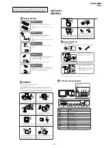
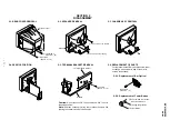
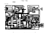
2-5. TERMINAL BRACKET REMOVAL
SECTION 2
DISASSEMBLY
2-1. REAR COVER REMOVAL
2-2. SPEAKER REMOVAL
2-3. CHASSIS ASSY REMOVAL
2-4. SERVICE POSITION
Caution:
Do not take out CRT support block while TV set in
standing position.
Note:
Undress necessary wires that creates tension while
placing the chassis into Service Position.
1
Six screws
(+BVTP 4
×
16)
1
Two screws
(+BVTP 4
×
16)
2
Rear cover
Speaker
1
Two screws, step tapping
2
Two screws, step tapping
A board
Terminal board bracket
One screw
(+BVTP 4
×
16)
2-6. REPLACEMENT OF PARTS
For replacements of Bar optical,unscrew them,
exchange with new parts and fix them with
screws respectively.
2-6-2. Replacement of Power Button
2-6-1. Replacement of Bar Optical
One screw
(+BVTP 3
×
8)
1
Push the claw to direction
of arrow and remove
2
Spring compression
3
Power Button


