4-2(E)
SX-M700
4-2. TROUBLESHOOTING PROCEDURE
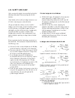
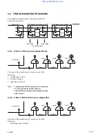
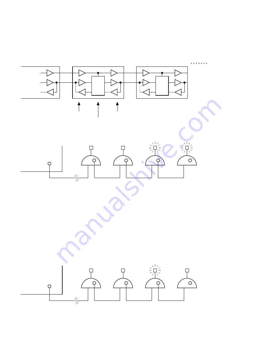
The signal flows between the control unit and the D/C
units are shown below.
4-2-1. If Error-1 Occurs in Connected Units
The cause of the trouble may be located in one of the
following:
1. Output stage of unit A
2. Cable B is broken
3. Input stage of unit B
Note :
A maximum of 15 D/C units can be connected
to a control unit. If 16 D/C units are
connected, the 16th unit and subsequent units
cause Error-1.
4-2-2. If Error-1 to Error-3 Occurs in a Single Unit
The cause of the trouble may be located in one of the
following:
Processing stage of unit B
Control Unit
D/C (delegate and chairman) Unit 0
D/C (delegate and chairman) Unit 1
Process
Process
Input stage
Processing stage
Output stage
Control Unit
Cable A
Cable B
Cable C
Unit A
Unit B
Unit C
Control Unit
Cable A
Unit A
Unit B
Unit C
Cable B
Cable C
Summary of Contents for SX-M100
Page 75: ...SX M700 6 12 TMP68301AFR 16 TOSHIBA http getMANUAL com ...
Page 111: ...8 2 8 2 SX M700 SX M700 AUDIO SX M700 BLOCK SX M700 BLOCK AUDIO BLOCK ...
Page 112: ...8 3 8 3 SX M700 SX M100 BLOCK SX M100 BLOCK SX M100 AUDIO AUDIO BLOCK ...
Page 113: ...8 4 8 4 SX M700 SX E120 DIGITAL SX E120 BLOCK SX E120 BLOCK DIGITAL BLOCK ...
Page 114: ...8 5 8 5 SX M700 SX E120 BLOCK SX E120 BLOCK SX E120 AUDIO AUDIO BLOCK ...
Page 115: ...8 6 8 6 SX M700 SX T100 AU 202 SX T100 BLOCK SX T100 BLOCK AU 202 BLOCK http getMANUAL com ...
Page 116: ...8 7 8 7 SX M700 SXA 120 BLOCK SXA 120 BLOCK SXA 120 AUDIO CPU 188 BLOCK ...
Page 120: ......
Page 126: ......
Page 128: ......
Page 130: ......
Page 132: ......
Page 136: ......

