2-8(E)
SX-M700
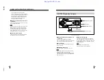
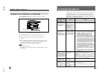
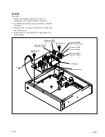
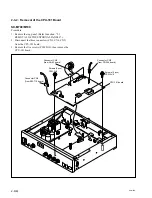
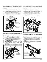
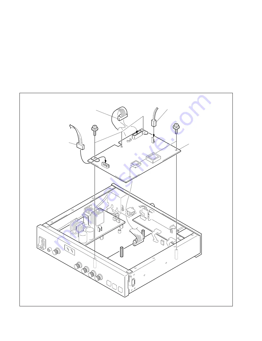
2-3-2. Removal of the CPU-181 Board
SX-M700/M100
Procedure
1. Remove the top panel. (Refer to section, “2-1.
REMOVAL OF THE EXTERNAL PANELS”.)
2. Disconnect the three connectors (CN3, CN4, CN5)
from the CPU-181 board.
3. Remove the five screws (PSW 3
x
8), then remove the
CPU-181 board.
Connector CN5
(from AA-93 board)
Screws (3 pcs)
PSW 3
x
8
Connector CN4
(from SW-710 board)
Connector CN3
(from PS-364 board)
Screws (2 pcs)
PSW 3
x
8
CPU-181 board
Summary of Contents for SX-M100
Page 75: ...SX M700 6 12 TMP68301AFR 16 TOSHIBA http getMANUAL com ...
Page 111: ...8 2 8 2 SX M700 SX M700 AUDIO SX M700 BLOCK SX M700 BLOCK AUDIO BLOCK ...
Page 112: ...8 3 8 3 SX M700 SX M100 BLOCK SX M100 BLOCK SX M100 AUDIO AUDIO BLOCK ...
Page 113: ...8 4 8 4 SX M700 SX E120 DIGITAL SX E120 BLOCK SX E120 BLOCK DIGITAL BLOCK ...
Page 114: ...8 5 8 5 SX M700 SX E120 BLOCK SX E120 BLOCK SX E120 AUDIO AUDIO BLOCK ...
Page 115: ...8 6 8 6 SX M700 SX T100 AU 202 SX T100 BLOCK SX T100 BLOCK AU 202 BLOCK http getMANUAL com ...
Page 116: ...8 7 8 7 SX M700 SXA 120 BLOCK SXA 120 BLOCK SXA 120 AUDIO CPU 188 BLOCK ...
Page 120: ......
Page 126: ......
Page 128: ......
Page 130: ......
Page 132: ......
Page 136: ......


