1
VPL-CS5A/CS6/CX6/EX1
Table of Contents
1. Service Overview
1-1.
Appearance Figure ...................................................................................... 1-1
1-2.
Board Locations .......................................................................................... 1-1
1-3.
Disassembly ................................................................................................ 1-2
1-3-1.
Top Panel Assy Removal ........................................................... 1-2
1-3-2.
Side Panel Assy and L, NR, H2, Q Boards Removal ................ 1-2
1-3-3.
Power Block (Lamp) Removal ................................................... 1-3
1-3-4.
DC Fan Removal ........................................................................ 1-3
1-3-5.
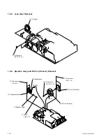
Lens Gear Removal .................................................................... 1-4
1-3-6.
Speaker Assy and DC Fan (Sirocco) Removal .......................... 1-4
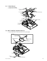
1-3-7.
C Board Removal ....................................................................... 1-5
1-3-8.
MSC and MS (VPL-CX6) Boards Removal .............................. 1-5
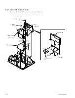
1-3-9.
GA and GB Boards Removal ..................................................... 1-6
1-3-10. Opt Unit Assy and Lamp Assy Removal ................................... 1-7
1-3-11. PS Con Aperture (VPL-EX1) and S In-polarizer (R), (G), (B)
Removal ..................................................................................... 1-7
1-3-12. Projection Lens Assy, Lamp Duct Assy and
U Board Removal ....................................................................... 1-8
1-3-13. S Prism Block Assy and
S Out-pre-polarizer (R), (G), (B) Removal ................................ 1-9
1-3-14. DC Fan (Sirocco) and V Board Removal ................................ 1-10
1-3-15. S Board Removal ..................................................................... 1-11
1-3-16. Extension Board and Extension Connectors ............................ 1-12
1-3-17. Extension Board and Extension Connectors Connection ......... 1-13
1-3-18. Warning on Power Connection ................................................ 1-14
2. Electrical Adjustments
2-1.
Preparation .................................................................................................. 2-1
2-1-1.
Required Equipment ................................................................... 2-1
2-1-2.
Opt Unit Adjustment .................................................................. 2-1
2-1-3.
How to Enter the Factory Mode ................................................. 2-2
2-2.
V COM Adjustment .................................................................................... 2-2
2-3.
Initial Values of Adjustment Items ............................................................. 2-3
2-4.
Service Know-How ................................................................................... 2-11
2-4-1.
When the S Prism Block Is Replaced ...................................... 2-11
2-4-2.
When the C Board Is Replaced ................................................ 2-11
2-4-3.
When the Adjuster Assy Is Returned
by the Emergency Mode .......................................................... 2-11
2-5.
White Balance Adjustment ....................................................................... 2-12
2-5-1.
HIGH Mode of INPUT-A ........................................................ 2-12
2-5-2.
LOW Mode of INPUT-A ......................................................... 2-12
2-5-3.
HIGH Mode of VIDEO ............................................................ 2-12
2-5-4.
LOW Mode of VIDEO ............................................................. 2-12
2-6.
Memory Structure ..................................................................................... 2-13

