


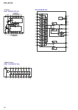


STR-KS370
41
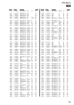
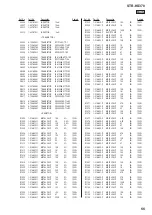
Pin No.
Pin Name
I/O
Description
1
DAMP_SCDT/DIR_DIN
O
Serial data output to the digital audio interface receiver and stream processor
2
DAMP_SHIFT/
DIR_CLK
O
Serial data transfer clock signal output to the digital audio interface receiver and stream
processor
3
CEC_DI
I
CEC serial data input from the HDMI connector
4
SIRCS_IN
I
SIRCS signal input from the remote control receiver
5
DSP_MOSI
O
Serial data output to the DSP
6
DSP_MISO
I
Serial data input from the DSP
7
DSP_SPICLK
O
Serial data transfer clock signal output to the DSP
8
BYTE
I
External data bus width selection signal input terminal “L”: 16 bit Fixed at “L” in this set
9
CNVss
I
Processor mode selection signal input terminal “L”: single chip mode
Fixed at “L” in this set
10
DIR_XSTATE
I
Clock change status input from the digital audio interface receiver
11
DCAC ON/OFF
I
Calibration microphone connection detection signal input terminal
“H”: calibration microphone is connected
12
RESET
I
System reset signal input from the reset signal generator “L”: reset
For several hundreds msec. after the power supply rises, “L” is input, then it change to “H”
13
Xout
O
Main system clock output terminal (5 MHz)
14
Vss
-
Ground terminal
15
Xin
I
Main system clock input terminal (5 MHz)
16
Vcc1
-
Power supply terminal (+3.3V)
17
NMI
I
Non-maskable interrupt signal input terminal
18
DIR_ZERO
I
Zero data detection signal input from the digital audio interface receiver
19
DIR_CSFLAG
I
Channel status 48 head bit update
fl
ag input from the digital audio interface receiver
20
DRIVE_OCP(DIAG)
I
Shut down signal input from the power ampli
fi
er “L”: shut down
21
PCM_MULTI
O
DSP input data selection signal output terminal “L”: A/D converter data , “H”: LPCM data
22
CEC_DO
O
CEC serial data output to the HDMI connector
23
P_CONT2
O
Power supply on/off control signal output terminal “H”: power on
24
DIR_HCE
O
Chip enable signal output to the digital audio interface receiver
25
NO USED
-
Not used
26
DSP_SPIDS
O
Device selection signal output to the DSP
27
DIR_ERROR
I
Error detection signal input from the digital audio interface receiver “H”: error
28
FAN_CTRL
-
Not used
29
I2C_CLK
I/O
Two-way I2C clock bus terminal (for debug)
30
I2C_DATA
I/O
Two-way I2C data bus terminal (for debug)
31
DMPORT_TX_OUT
O
Serial data output to the DMPORT connector
32
DMPORT_RX_IN
I
Serial data input from the DMPORT connector
33
CLK1
-
Not used
34
S-AIR_SRC_MUTE
O
Sampling rate converter muting signal output to the wireless transmitter (EZW-T100)
35
HDMI_TXD
O
Serial data output to the HDMI controller
36
HDMI_RXD
I
Serial data input from the HDMI controller
37, 38
NO USED
-
Not used
39
P_CONT3
O
Power supply on/off control signal output terminal for wireless transmitter (EZW-T100)
“H”: power on
40
ST_CE
O
Chip enable signal output to the tuner (FM/AM)
41
ST_CLK
O
Serial data transfer clock signal output to the tuner (FM/AM)
42
RDS_DATA
I
RDS serial data input from the tuner (FM/AM)
43
ST_DI
I
Serial data input from the tuner (FM/AM)
44
TUNED
I
Tuned detection signal input from the tuner (FM/AM) “L”: tuned
45
ST_DO
O
Serial data output to the tuner (FM/AM)
46
DC_DET
I
Over load detection signal input terminal “L”: over load
47
P_CONT4
O
Power supply on/off control signal output terminal for DSP “H”: power on
48, 49
NO USED
-
Not used
50
P_CONT1
O
Power supply on/off control signal output terminal “H”: power on
51
DIGITAL SELECTOR
IN A
O
Digital audio input signal selection signal output terminal
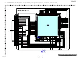
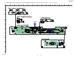
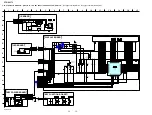
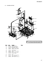
MAIN BOARD IC1005 R5F3640MDFAR (SYSTEM CONTROLLER)