


4
STR-K7000
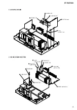
SECTION 1
GENERAL
This section is extracted
from instruction manual.
5
US
Gettin
g Sta
rted
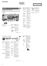
Description and location of parts
Front panel
To remove the cover
Press PUSH.
When you remove the cover, keep it out of
reach from children.
Getting Started
Receiver
?/1
AUTO CAL MIC
SPEAKERS
(OFF/A/B/A+B)
PHONES
VIDEO 3 IN/PORTABLE AV IN
VIDEO
L AUDIO R
MEMORY/
ENTER
TUNING
MODE
TUNING
2CH
A.F.D.
MOVIE
MUSIC
MULTI CH IN
MUTING
DISPLAY
INPUT MODE
INPUT SELECTOR
MASTER VOLUME
MULTI CHANNEL DECODING
3
6
8
4
7
5
q;
9
qa
qs
qd
w;
qf
qg
qh
qj
qk
PUSH
ql
1
2
Name
Function
A
?
/
1
Press to turn the receiver on
or off (page 29, 37, 38, 53,
79).
B
SPEAKERS
(OFF/A/B/A+B)
Press to select OFF, A, B,
A+B of the front speakers
(page 30).
C
Display
The current status of the
selected component or a list
of selectable items appears
here (page 7).
D
MULTI
CHANNEL
DECODING
lamp
Lights up when multi
channel audio is decoded
(page 38).
continued
6
US
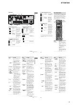
Name
Function
E
Remote sensor
Receives signals from
remote commander.
F
DISPLAY
Press to select information
displayed on the display
(page 67).
G
INPUT MODE
Press to select the input
mode when the same
components are connected
to both digital and analog
jacks (page 64).
H
MASTER
VOLUME
Turn to adjust the volume
level of all speakers at the
same time (page 34, 35,
37, 38).
I
MUTING
Press to mute the sound
(page 35).
J
MULTI CH IN
Press to select the audio
directly from the
components connected to
the MULTI CH IN jacks
(page 35).
K
INPUT
SELECTOR
Turn to select the input
source to playback (page
35, 37, 38, 54, 56, 64, 66,
68).
L
MOVIE,
MUSIC
Press to select sound fields
(MOVIE, MUSIC) (page
50).
M
A.F.D.
Press to select A.F.D.
mode (page 48).
N
2CH
Press to select 2CH
STEREO mode (page 52,
53).
O
/–
Press to scan a station
(page 54, 55).
P
TUNING MODE
Press to select the tuning
mode (page 56, 79).
Q
MEMORY/ENTER
Press to store a station or
enter the selection when
selecting the settings
(page 29).
Name
Function
R
VIDEO 3 IN/
PORTABLE AV IN
jacks
To connect a camcorder or
video game (page 27, 35).
S
AUTO CAL MIC
jack
Connects to the supplied
ECM-AC2 optimizer
microphone for the Auto
Calibration function (page
31).
T
PHONES jack
Connects to a headphone
(page 75).
7
US
Gettin
g Sta
rted
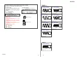
About the indicators on the display
MEMORY
L
C
R
SL
S
SR
SW
LFE
SP A
SP B
CAT
STEREO MONO
D.RANGE
SLEEP OPT COAX
HDMI
DIGITAL
;
DTS
;
PRO LOGIC II
9
qf
qg
qs
qd
qa
q;
2
1
4
3
5
6
7
8
Name
Function
A
SW
Lights up when the audio signal
is output from the SUB
WOOFER jack.
B
LFE
Lights up when the disc being
played back contains an LFE
(Low Frequency Effect)
channel and the LFE channel
signal is actually being
reproduced.
C
SP A/SP B
Lights up according to the
speaker system used. However,
these indicators do not light up
if the speaker output is turned
off or if a headphone is
connected.
D
;
DIGITAL
Lights up when Dolby Digital
signals are input.
Note
When playing a Dolby Digital
format disc, be sure that you
have made digital connections
and that INPUT MODE is not
set to “ANALOG” (page 64).
E
;
PRO
LOGIC (II)
Lights up when the receiver
applies Pro Logic processing to
2 channel signals in order to
output the center and surround
channel signals. “
;
PRO
LOGIC II” lights up when the
Pro Logic II Movie or Music
decoder is activated.
Note
Dolby Pro Logic and Dolby Pro
Logic II decoding do not
function for DTS format
signals.
Name
Function
F
DTS
Lights up when DTS signals are
input.
Note
When playing a DTS format
disc, be sure that you have made
digital connections and that
INPUT MODE is not set to
“ANALOG” (page 64).
G
MEMORY
Lights up when a memory
function, such as Preset
Memory (page 55), etc., is
activated.
H
Preset
station
indicators
Lights up when using the
receiver to tune in radio stations
you have preset. For details on
presetting radio stations, see
page 55.
I
Tuner
indicators
Lights up when using the
receiver to tune in radio stations
(page 53), etc.
J
D.RANGE
Lights up when dynamic range
compression is activated (page
40).
K
HDMI
Flashes when you select
“HDMI A.” in the VIDEO
menu (page 65).
L
COAX
Lights up when INPUT MODE
is set to “AUTO” and the source
signal is a digital signal being
input through the COAXIAL
jack, or when INPUT MODE is
set to “COAX IN” (page 64).
continued
8
US
Name
Function
M
OPT
Lights up when INPUT MODE
is set to “AUTO” and the source
signal is a digital signal being
input through the OPTICAL
jack, or when INPUT MODE is
set to “OPT IN” (page 64).
N
SLEEP
Lights up when the sleep timer
is activated (page 67).
O
Playback
channel
indicators
L
R
C
SL
SR
S
The letters (L, C, R, etc.)
indicate the channels being
played back. The boxes around
the letters vary to show how the
receiver downmixes the source
sound.
Front Left
Front Right
Center (monaural)
Surround Left
Surround Right
Surround (monaural or the
surround components obtained
by Pro Logic processing)
Example:
Recording format (Front/
Surround): 3/2.1
Sound Field: A.F.D. AUTO
L
C
R
SL
SR
SW


