


3
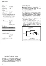
STR-K7000
TABLE OF CONTENTS
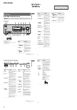
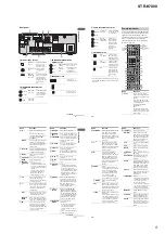
1. GENERAL
Description and location of parts ............................................. 4
2. DISASSEMBLY
2-1. Case ..................................................................................... 7
2-2. Front Panel Section ............................................................. 8
2-3. Back Panel Section .............................................................. 8
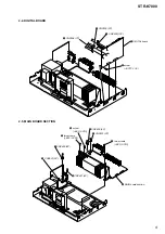
2-4. DIGITAL Board .................................................................. 9
2-5. MAIN Board Section .......................................................... 9
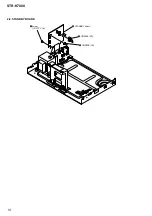
2-6. STANDBY Board ............................................................. 10
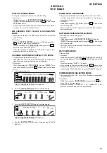
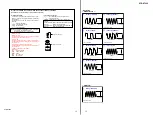
3. TEST MODE
..................................................................... 11
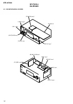
4. DIAGRAMS
4-1. Circuit Boards Location .................................................... 12
4-2. Block Diagram – Tuner/Audio Section – .......................... 14
4-3. Block Diagram – Digital Section – ................................... 15
4-4. Block Diagram – Video Section – ..................................... 16
4-5. Block Diagram – XM Section – ........................................ 17
4-6. Block Diagram – Key/Display Section – .......................... 18
4-7. Block Diagram – Power Section – .................................... 19
4-8. Printed Wiring Boards – Main Section – .......................... 20
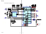
4-9. Schematic Diagram – Main Section (1/3) – ...................... 21
4-10. Schematic Diagram – Main Section (2/3) – ...................... 22
4-11. Schematic Diagram – Main Section (3/3) – ...................... 23
4-12. Printed Wiring Board – Digital Section (1/2) – ................ 24
4-13. Printed Wiring Board – Digital Section (2/2) – ................ 25
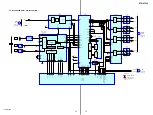
4-14. Schematic Diagram – Digital Section (1/5) – ................... 26
4-15. Schematic Diagram – Digital Section (2/5) – ................... 27
4-16. Schematic Diagram – Digital Section (3/5) – ................... 28
4-17. Schematic Diagram – Digital Section (4/5) – ................... 29
4-18. Schematic Diagram – Digital Section (5/5) – ................... 30
4-19. Printed Wiring Boards
– Front B/Center Speaker Section – .................................. 31
4-20. Schematic Diagram
– Front B/Center Speaker Section – .................................. 32
4-21. Printed Wiring Boards – Video Section – ......................... 33
4-22. Schematic Diagram – Video Section – .............................. 34
4-23. Printed Wiring Board – HDMI Section – .......................... 35
4-24. Schematic Diagram – HDMI Section – ............................ 36
4-25. Printed Wiring Board – XM Section – .............................. 37
4-26. Schematic Diagram – XM Section – ................................. 38
4-27. Printed Wiring Board – ADCC Section – ......................... 39
4-28. Schematic Diagram – ADCC Section – ............................ 39
4-29. Printed Wiring Boards – Display Section – ...................... 40
4-30. Schematic Diagram – Display Section – ........................... 41
4-31. Printed Wiring Board – Power Section – .......................... 42
4-32. Schematic Diagram – Power Section – ............................. 43
5. EXPLODED VIEWS
5-1. Case Section ...................................................................... 53
5-2. Front Panel Section ........................................................... 54
5-3. Back Panel Section ............................................................ 55
5-4. Chassis Section ................................................................. 56
6. ELECTRICAL PARTS LIST
........................................ 57


