background image

11

11

STR-K700

STR-K700

• Waveforms

– DIGITAL Board –

For Schematic Diagrams.
Note:
• All capacitors are in 

µ

F unless otherwise noted.  (p: pF)

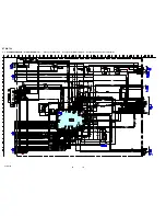
50 WV or less are not indicated except for electrolytics and
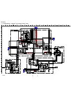
tantalums.

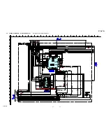
• All resistors are in 

  and 

1

/

4


W or less unless otherwise

specified.

•     %

: indicates tolerance.

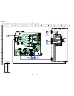
•        

f

: internal component.

2

: nonflammable resistor.

5

: fusible resistor.

C

: panel designation.

A

: B+ Line.

B

: B+ Line.

• Voltages and waveforms are dc with respect to ground un-

der no-signal (detuned) conditions.
No mark : FM

• Voltages are taken with a VOM (Input impedance 10 M

).

Voltage variations may be noted due to normal production
tolerances.

• Waveforms are taken with a oscilloscope.
• Circled numbers refer to waveforms.

• Signal path.

F

: FM

J

: ANALOG

c

: DIGITAL

For Printed Wiring Boards.
Note:

X

: parts extracted from the component side.

•        

a

: Through hole.

•        

f

: internal component.

: Pattern from the side which enables seeing.

• Indication of transistor.

THIS NOTE IS COMMON FOR PRINTED WIRING BOARDS AND SCHEMATIC DIAGRAMS.
(In addition to this, the necessary note is printed in each block.)

Caution:
Pattern face side:

Parts on the pattern face side seen from

(Side A)

the pattern face are indicated.

Parts face side:

Parts on the parts face side seen from

(Side B)

the parts face are indicated.

1


IC1501


9


(MCLK1) 

1 V/DIV, 40 ns/DIV

72 ns

3.4 Vp-p

2


IC1101


id


(X1) 

1 V/DIV, 20 ns/DIV

41.6 

n

s

4.2 Vp-p

3


IC1301


ws


(XIN) 

1 V/DIV, 40 ns/DIV

81 ns

4.4 Vp-p

C

B

These are omitted.

E

Q

B

These are omitted.

C

E

   Note:

The components identi-
fied by mark 

0

  or dot-

ted line with mark 

0

 are

critical for safety.
Replace only with part
number specified.

   Note:

Les composants identifiés
par une marque 

0

 sont cri-

tiques pour la sécurité.
Ne les remplacer que par une
piéce por tant le numéro
spécifié.

SECTION 3

DIAGRAMS

• Circuit Boards Location

DIGITAL board 

MAIN board

STANDBY board

POWER board

ADCC board

HEADPHONE board

DISPLAY board

Summary of Contents for STR-K700 - Fm Stereo/fm-am Receiver

Page 1: ...s 1 kHz THD 0 7 FRONT2 85 W ch CENTER2 85 W SUR2 85 W ch 6 ohms 100 Hz THD 0 7 SUB WOOFER2 85 W 6 ohms 1 kHz THD 10 FRONT2 133 W ch CENTER2 133 W SUR2 133 W ch 6 ohms 100 Hz THD 10 SUB WOOFER2 135 W 1 Measured under the following conditions 2 Depending on the sound field settings and the source there may be no sound output Power requirements 120 V AC 60 Hz Inputs Analog Inputs Digital Reproduction...

Page 2: ... so be careful Strong viscosity Unleaded solder is more viscou s sticky less prone to flow than ordinary solder so use caution not to let solder bridges occur such as on IC pins etc Usable with ordinary solder It is best to use only unleaded solder but unleaded solder may also be added to ordinary solder About area codes The area code of the receiver you purchased is shown on the lower right porti...

Page 3: ...part having a return to chassis must not exceed 0 5 mA 500 microamperes Leakage current can be measured by any one of three methods 1 A commercial leakage tester such as the Simpson 229 or RCA WT 540A Follow the manufacturers instructions to use these instruments 2 A battery operatedAC milliammeter The Data Precision 245 digital multimeter is suitable for this job 3 Measuring the voltage drop acro...

Page 4: ... of selectable items appears here F DISPLAY Press to select information displayed on the display G INPUT MODE Press to select the input mode when the same components are connected to both digital and analog jacks H MASTER VOLUME Turn to adjust the volume level of all speakers at the same time I INPUT SELECTOR Turn to select the input source to playback J Remote sensor Receives signals from remote ...

Page 5: ...mat disc be sure that you have made digital connections and that INPUT MODE is not set to ANALOG G MEMORY Lights up when a memory function such as Name Input Preset Memory etc is activated H Preset station indicators Lights up when using the receiver to tune in radio stations you have preset For details on presetting radio stations I Tuner indicators Lights up when using the receiver to tune in ra...

Page 6: ...INPUT section OPTICAL IN jack Connects to a DVD player etc The COAXIAL jack provides a better quality of loud sound COAXIAL IN jack B ANTENNA section FM ANTENNA Connects to the FM wire antenna supplied with this receiver AM ANTENNA Connects to the AM loop antenna supplied with this receiver C AUDIO INPUT section AUDIO IN jack Connects to a CD player etc D SPEAKER section Connects to the speakers a...

Page 7: ...e time it will turn off the receiver and other components SYSTEM STANDBY Note The function of the AV 1 switch changes automatically each time you press the input buttons C B TV 1 Press TV 1 and TV P at the same time to turn the TV on or off 1 Press to turn the receiver on or off To turn off all components press 1 and AV 1 A at the same time SYSTEM STANDBY C Input buttons Press one of the buttons t...

Page 8: ...ess to skips tracks of the CD player DVD player or tape deck REPLAY ADVANCE Press to replay the previous scene or fast forward the current scene of the VCR or DVD player m M Press to search tracks in the forward backward direction of the DVD player or to fastforward rewind of the VCR CD player or tape deck H Press to start playback of the VCR CD player DVDplayer or tape deck X Press to pause playb...

Page 9: ... tuner or CD player or to select channel numbers of the Digital CATV terminal CLEAR Press to clear a mistake when you press the incorrect numeric buttons or to return to continuous playback etc of the satellite tuner or DVD player U Numeric buttons number 5 Press to preset tune to preset stations or to select track numbers of the CD player or DVD player or to select channel numbers of the VCR or s...

Page 10: ... simultaneously press the power 1 button to turn on the main power 2 The model name destination and the software version are displayed KEY CHECK MODE Button check Procedure 1 While depressing the A F D and the DISPLAY buttons simultaneously press the power 1 button to turn on the main power REST 08 appears 2 Every pressing of any button other than 1 counts down the buttons The buttons which are al...

Page 11: ...l component Pattern from the side which enables seeing Indication of transistor THIS NOTE IS COMMON FOR PRINTED WIRING BOARDS AND SCHEMATIC DIAGRAMS In addition to this the necessary note is printed in each block Caution Pattern face side Parts on the pattern face side seen from Side A the pattern face are indicated Parts face side Parts on the parts face side seen from Side B the parts face are i...

Page 12: ...A1 45 DATA2 46 14 VOUT1 12 VOUT3 11 VOUT4 ANALOG SOUND SL ADFL 13 LIN 16 19 20 21 SL C 32 SWOUT SBL SLIN CIN SWIN A 98 97 95 96 99 100 94 1 DO DI CLK CE ERROR XSTATE CKSEL1 DATA0 92 LRCK_SW 20 HCLK 4 HCS 5 HACN 7 PM 3 BST 6 XRST 8 GP12 10 PCM1608_RST ADCC_DSP_IN 45 ADCC_ANA_OGUE_IN 12 PCM1608_ML 13 PCM1608_MC 14 PCM1608_MDI 15 PCM1608_MDO 5 6 29 30 J402 J2000 J400 VIDEO 1 VIDEO 2 SA CD CD DVD OPTI...

Page 13: ... POWER KEY 56 1 S152 77 RSTX 48 STOP 54 SIRCS 63 FUSE DETECT REMOTE CONTROL RECEIVER 1 IC102 D910 913 AC IN T902 RY901 D915 D914 RELAY DRIVE Q901 D920 923 23 VCC5 84 VCC3 7V REG 3 2 7V REG 1 3 AUDIO 7V IC821 IC822 POWER RY 58 RELAY B D804 807 82 83 X0 X1 X1101 24MHz F1 F2 L SL SL C A IN1 6 SBL J700 FLUORESCENT INDICATOR TUBE FL101 59 FL_DATA 60 FL_CLK 47 FL_LAT 7 DIN 8 CLK 9 STB 14 29 SEG1 16 42 3...

Page 14: ...D1301 C 2 D1302 C 2 IC1101 D 5 IC1111 C 6 IC1131 E 5 IC1301 B 2 IC1303 C 2 IC1401 E 2 IC1452 D 3 IC1501 D 4 IC1502 B 4 IC1503 D 4 See page 11 for Circuit Boards Location IC1301 IC1303 IC1502 IC1101 IC1111 IC1131 IC1503 IC1401 IC1452 IC1501 1 12 36 37 25 48 24 13 1 12 36 25 13 24 48 37 1 30 31 90 91 120 61 60 1 3 4 5 1 2 A B C D E 3 4 5 6 7 ...

Page 15: ...C 3 IC1902 B 4 IC1904 C 3 Uses unleaded solder See page 11 for Circuit Boards Location VIDEO 2 IN DVD IN COXIAL DIGITAL 1 2 3 5 1 1 4 5 1 5 6 8 1 2 A B C D E F 3 4 5 6 7 8 9 D E STANDBY BOARD CNP801 Page 24 G MAIN BOARD CNP501 Page 19 F C MAIN BOARD CNP502 Page 19 DISPLAY BOARD CNS100 Page 25 B MAIN BOARD CNP503 Page 19 A MAIN BOARD CNP503 Page 19 MAIN BOARD CN504 Page 19 TN1 TUNER UNIT IC1901 IC1...

Page 16: ...3 R1531 R1545 C1508 R1543 R1542 R1571 R1572 R1570 R1136 C1515 C1513 C1514 R1041 R1042 R1140 R1134 R1135 C1353 C1361 R1359 R1150 R1541 C1502 R1511 R1533 R1532 C1509 R1540 R1539 R1538 R1537 R1536 R1535 C1352 J1301 IC1301 D1004 D1003 IC1303 D1302 D1301 JR1020 IC1502 IC1503 FB1503 D1112 D1113 D1114 R1363 TP1011 12 288MHz 10k 220 220 220 220 220 220 220 220 220 220 220 220 220 220 220 220 220 10k 100 2...

Page 17: ...01 C1404 C1402 FB1405 C1401 C1568 FB1452 C1450 FB1453 C1468 R1436 C1458 CNS501 R1475 R1472 R1471 R1493 R1494 R1495 IC1452 IC1401 R1445 R1460 R1492 R1461 R1491 R1470 R1426 C1418 IC1001 C1406 470 10V 0 1 10 50V 10 10 50V 10 50V 10 50V 1k 1k 1k 1k 0 0022 0 0022 0 0022 0 0022 0 0022 10 50V 4 7 50V 10 50V 10k 10k 100 0 1 0 1 470p 470p 0 1 2 2k 1k 0 1 47 16V 0 1 0 0022 0 1 10 50V 1k 10 50V 15P PCM1602AP...

Page 18: ...0 R1039 X1101 C1299 C1149 R1096 CNP503 R1112 CNP505 R1201 R1113 R1261 R1120 R1137 R1142 R1151 R1168 C1121 C1142 C1620 R1636 C1103 R1035 CNS502 R1167 D1107 D1111 D1110 IC1902 C1913 IC1901 C1906 C1908 IC1904 D1001 R1635 R1179 R1459 R1458 R1180 R1088 IC1131 R1163 IC1111 IC1101 R1260 C1100 1k 10k 39k 39k 10k 1k 3 3k 220p 0 01 470 10V 470 10V 100k 100 100 100 100 100 100 100 100 100 100 100 100 10k 10k...

Page 19: ...G 12 Q654 G 14 Q655 G 14 Q656 G 13 Q657 F 11 Q701 F 3 Q702 H 4 Q703 G 3 Q704 G 4 Q705 G 4 Q706 G 4 Ref No Location Q707 G 2 Q708 C 9 Q751 F 5 Q752 H 6 Q753 G 5 Q754 G 6 Q755 G 6 Q756 F 5 Q801 E 14 Q851 E 11 Q852 E 9 Q860 F 6 Q861 F 7 Q862 F 9 Q881 E 12 Q882 E 12 Q883 E 12 Uses unleaded solder See page 11 for Circuit Boards Location H ADCC BOARD CNP2000 Page 23 G DIGITAL BOARD CNS501 Page 15 I POWE...

Page 20: ...26 J402 J400 C471 R406 CNP501 CNP502 C424 R451 R402 R403 R452 R453 R454 R404 C484 C482 Q471 Q560 D752 1k 680 1k 2 2k 10 50V 10 50V 2 2 50V 2 2 50V 2 2 50V 2 2 50V 2 2 50V 4 7 50V 4 7 50V 4 7 50V 4 7 50V 100 0 1 0 001 0 001 220 4 7k 4 7 50V 1k BOARD IN WIRE TO TP2 M61542FP 2 2 50V 4 7 50V 100 10V 100 15P 10P 4 7 50V 1k 1k 1k 1k 1k 1k 1k 0 1 0 1 2SD2144S TP UVW 2SC1740S QRT 1SS133T 72 0 33 0 22 2 2k...

Page 21: ... 100 10V 100 10V 100p 560 100 100 4 7k 1 5k 15k 15k 22k 22k 68k 47k 220p 0 01 0 022 100 100 68k 4 7k 220p 1 5k 15k 22k 22k 10 50V 0 01 47k 10 0 022 100 220p 1 5k 15k 22k 22k 10 50V 0 01 15k 47k 0 022 68k 22k 22k 0 01 15k 10 50V 47k 10 0 022 15k 68k 1 5k 220p 4 7k 100 560 560 100 220p 1 5k 68k 15k 0 01 15k 22k 22k 82 82 82 10 100V 10 100V 220 16V 10 50V 10k 6 8k 39k 1k 3p 500V 3p 500V 3 3k 3 3k 3 3...

Page 22: ...1 D901 RY901 F901 T902 JW901 Q911 D914 D915 D2014 D2013 4 7 22k 3P 5P 47 35V 47 35V 47 35V AK04V1 47k 0 47 50V 33k 10k 1 4 7k 47k 10k 10k 10k 33k 220k 10k 470k 3300 16V 10k 10EDB40 TA2B5 10EDB40 TA2B5 10EDB40 TA2B5 10EDB40 TA2B5 10EDB40 TA2B5 10EDB40 TA2B5 10EDB40 TA2B5 10EDB40 TA2B5 0 22 5P HZ6 8BP TK TA79007S DTA124ESA TP NJM4565D 2P JW 0 22 0 22 0 1 0 1 0 1 TA7807S 0 22 0 22 0 22 0 22 47 25V 47...

Page 23: ...3 12 PRINTED WIRING BOARDS ADCC BOARD HEADPHONE BOARD Uses unleaded solder See page 11 for Circuit Boards Location L MAIN BOARD CN701 Page 19 H MAIN BOARD CNP732 Page 19 IC2000 1 4 AUTO CAL MIC PHONES 1 4 1 2 A B C D 3 4 5 6 7 ...

Page 24: ...1 1 2 A B C D E F 3 4 5 6 7 8 9 10 I MAIN BOARD CNP901 Page 19 K MAIN BOARD CNP902 Page 19 J MAIN BOARD CNP916 Page 19 D DIGITAL BOARD CNP505 Page 15 T901 POWER TRANSFORMER MAIN POWER TRANSFORMER SUB Semiconductor Location Ref No Location D901 D 5 D910 B 6 D911 B 6 D912 B 6 D913 C 6 D914 C 6 D915 C 6 D920 E 4 D921 E 4 D922 E 4 D923 E 4 Q901 C 5 Q911 D 5 ...

Page 25: ...3 B 3 D104 B 3 D105 B 7 IC100 A 7 IC101 B 6 IC102 A 9 Q110 C 7 Uses unleaded solder See page 11 for Circuit Boards Location MASTER VOLUME INPUT SELECTOR INPUT MODE DISPLAY A F D MOVIE MUSIC DIMMER SLEEP 2CH 1 4 1 1 3 7 14 8 1 4 1 5 10 15 42 1 2 A B C D E F G H 3 4 5 6 7 8 9 10 11 12 13 14 C DIGITAL BOARD CNS505 Page 15 IC102 IC100 IC101 ...

Page 26: ...114 S115 S116 S117 S118 S119 S101 R101 R115 R116 R117 R118 R119 CNS100 CNP101 RV102 RV103 C110 FL101 R198 R199 IC102 CNP102 IC100 C111 C112 C109 82k JW 100 JW 10 100 100 100 JW 10 50V 10 50V JW TC74ACT08P 220p 220p 220p 220p 220p 220p 220p 220p 220p 220p 220p 220p 220p 220p 220p 0 22 0 22 0 22 0 22 0 22 0 22 0 22 0 22 0 22 220 220 330 470 330 470 19P 4P ENCODER ROTARY VOLUME ENCODER ROTARY INPUT S...

Page 27: ...4 5 44 8 9 10 46 17 22 21 20 30 35 25 26 27 28 29 32 33 34 16 45 13 14 15 47 40 41 48 CLK 39 XSEL CE DI EMPHA AUDIO DISEL SPDIF DINO DINI DIN2 6 D GND 7 DVDD 11 AVDD 12 AGND DOSEL0 R VIN LPF CKSEL0 XSTATE 18 DGND 19 DVDD XIN XOUT XMCK DVDD 31 DGND DO CSFLAG F0 P0 C0 F1 P1 C1 F2 P2 C2 VF P3 C3 LOCK BPSYNC ERROR DATAO DOSEL1 CKOUT BCK LRCK CKSEL1 MODE0 MODE1 42 DGND 43 DVDD XMODE TIMING MICROCOMPUTE...

Page 28: ...1452 PCM1602APT SYSTEM CLOCK MANAGER FUNCTION CONTROL INTERFACE SERIAL INPUT INTERFACE 4X 8X OVER SAMPLING DIGITAL FILTER WITH FUNCTION CONTROLLER ENHANCED MULTI LEVEL DELTA SIGMA MOJULE ZERO DETECT DAC LPF DAC LPF DAC LPF DAC LPF DAC LPF DAC LPF DAC LPF DAC LPF RST SCKI SCKO BCK TEST VDD DGND DATA1 DATA2 DATA3 ZEROA LRCK 37 38 39 40 42 43 44 45 46 47 48 41 ZERO1 GPO1 ZERO2 GPO2 ZERO3 GPO3 ZERO4 G...

Page 29: ...t latch 24 bit output latch 12 bit shift register Data selector 6 7 8 9 10 11 12 13 14 15 16 17 18 19 20 21 22 23 24 25 26 27 28 29 30 31 32 33 34 35 36 37 38 Serial interface OSC Timing generator key scan Display memory 24 bits x 12 words Key data memory 2 x 16 bits Command decoder segment driver Grid driver Multiplexed driver 39 40 41 42 43 44 LED1 LED2 LED3 LED4 OSC DOUT DIN CLK STB KEY1 KEY2 V...

Page 30: ...SLIGO CIGO CVIN CVC COUT SWOUT SWC SWVIN SWIGO SLOUT RECR2 RECR1 RECL1 LIGO LVIN LVC LOUT ROUT RVC RVIN RIGO SRIGO SRVIN RECL2 INL5 INR5 INL4 INR4 INL3 INR3 INL2 INR2 INL1 INR1 ADIFL ADIFR GND LIN RIN SLIN SRIN CIN SWIN GND GND DATA CLOCK DVDD AVCC GND AVEE 44 43 41 42 Volume 52 51 49 50 Volume 46 48 47 Volume MCU I F 1 2 3 4 5 6 STAND BY CIRCUIT PRE DRIVER PRE DRIVER DRIVER DRIVER 47kΩ 33Ω 33Ω 4 ...

Page 31: ...nal output to DSP 21 VOL_CLK O Clock signal output to the ASP 22 VOL_DATA_LATCH O Data output to the ASP 23 VCC5 Power supply 3 3V 24 SYS_MUTE O Muting and error signal output 25 ANA DIG O Analog signal or digital signal output terminal 26 NOT_USED Not used 27 FLASH2 O FLASH2 signal output not used 28 FLASH1 O FLASH1 signal output not used 29 SDA I EEPROM data signal input terminal 30 SCL O EEPROM...

Page 32: ...output 67 C SB_RY O Center speaker or Surround back speaker control signal output 68 REAR_RY O Rear speaker control signal output 69 NOT_USED Not used 70 NOT_USED Not used 71 NOT_USED Not used 72 NOT_USED Not used 73 DO I Frequency data signal input from the tuner 74 SLATCH O Latch signal output to the tuner 75 TUNED I Tuning a frequency signal input from the tuner 76 STEREO I Stereo tuning signal...

Page 33: ...TR K700 Pin No Pin Name I O Description 97 DI O Data signal output to DIR 98 DO I Data signal input from DIR 99 ERROR I PLL error muting signal input from DIR 100 XSTATE I XSTATE data signal input from DIR ...

Page 34: ...3 356 1 FRONT PANEL ASSY CND 4 4 977 358 01 CUSHION 5 3 087 053 01 BVTP2 6 3CR 4 1 FRONT PANEL SECTION Ref No Part No Description Remark Items marked are not stocked since they are seldom required for routine service Some delay should be anticipated when ordering these items Abbreviation CND Canadian model The components identified by mark 0 or dotted line with mark 0 are critical for safety Repla...

Page 35: ...04 6 702 391 01 IC MP1620 OPY MK 4 2 CHASSIS SECTION Q553 6 702 390 01 IC MN2488 OPY MK Q554 6 702 391 01 IC MP1620 OPY MK Q603 6 702 390 01 IC MN2488 OPY MK Q604 6 702 391 01 IC MP1620 OPY MK Q653 6 702 390 01 IC MN2488 OPY MK Q654 6 702 391 01 IC MP1620 OPY MK Q703 6 702 390 01 IC MN2488 OPY MK Q704 6 702 391 01 IC MP1620 OPY MK Q753 6 702 390 01 IC MN2488 OPY MK Q754 6 702 391 01 IC MP1620 OPY ...

Page 36: ... 685 646 79 SCREW BVTP 3X8 TYPE2 IT 3 CAPACITOR C1001 1 126 925 91 ELECT 470uF 20 10V C1002 1 100 566 91 CERAMIC CHIP 0 1uF 10 25V C1004 1 164 227 11 CERAMIC CHIP 0 022uF 10 25V C1005 1 100 566 91 CERAMIC CHIP 0 1uF 10 25V C1021 1 100 566 91 CERAMIC CHIP 0 1uF 10 25V C1022 1 126 925 91 ELECT 470uF 20 10V C1031 1 100 566 91 CERAMIC CHIP 0 1uF 10 25V C1032 1 126 925 91 ELECT 470uF 20 10V C1100 1 100...

Page 37: ...IP 0 1uF 10 25V C1505 1 100 566 91 CERAMIC CHIP 0 1uF 10 25V C1506 1 100 566 91 CERAMIC CHIP 0 1uF 10 25V C1507 1 100 566 91 CERAMIC CHIP 0 1uF 10 25V C1508 1 100 566 91 CERAMIC CHIP 0 1uF 10 25V C1509 1 100 566 91 CERAMIC CHIP 0 1uF 10 25V C1510 1 100 566 91 CERAMIC CHIP 0 1uF 10 25V C1511 1 100 566 91 CERAMIC CHIP 0 1uF 10 25V C1513 1 100 566 91 CERAMIC CHIP 0 1uF 10 25V C1514 1 100 566 91 CERAM...

Page 38: ...5 1 10W R1113 1 216 809 11 METAL CHIP 100 5 1 10W R1115 1 216 809 11 METAL CHIP 100 5 1 10W R1117 1 216 821 11 METAL CHIP 1K 5 1 10W R1118 1 216 821 11 METAL CHIP 1K 5 1 10W R1119 1 216 821 11 METAL CHIP 1K 5 1 10W R1120 1 216 821 11 METAL CHIP 1K 5 1 10W R1121 1 216 809 11 METAL CHIP 100 5 1 10W R1122 1 216 809 11 METAL CHIP 100 5 1 10W R1123 1 216 809 11 METAL CHIP 100 5 1 10W R1124 1 216 809 11...

Page 39: ...11 METAL CHIP 100 5 1 10W R1505 1 216 809 11 METAL CHIP 100 5 1 10W R1506 1 216 809 11 METAL CHIP 100 5 1 10W R1508 1 216 809 11 METAL CHIP 100 5 1 10W R1509 1 216 809 11 METAL CHIP 100 5 1 10W R1510 1 216 809 11 METAL CHIP 100 5 1 10W R1511 1 216 809 11 METAL CHIP 100 5 1 10W R1512 1 216 821 11 METAL CHIP 1K 5 1 10W R1513 1 216 833 11 METAL CHIP 10K 5 1 10W R1514 1 216 833 11 METAL CHIP 10K 5 1 1...

Page 40: ...5 1 4W R150 1 249 440 11 CARBON 82K 5 1 4W R153 1 247 807 31 CARBON 100 5 1 4W R172 1 247 807 31 CARBON 100 5 1 4W R173 1 247 807 31 CARBON 100 5 1 4W R174 1 247 807 31 CARBON 100 5 1 4W R175 1 249 393 11 CARBON 10 5 1 4W R198 1 249 381 11 CARBON 1 5 1 4W R199 1 249 381 11 CARBON 1 5 1 4W VARIABLE RESISTOR RV102 1 418 725 41 ENCODER ROTARY 12 TYPE MASTER VOLUME RV103 1 418 817 21 ENCODER ROTARY IN...

Page 41: ...uF 20 100V C701 1 126 963 11 ELECT 4 7uF 20 50V C702 1 128 809 11 CERAMIC 100PF 5 50V C703 1 128 809 11 CERAMIC 100PF 5 50V C704 1 102 233 00 CERAMIC 33PF 10 500V C706 1 107 583 11 CERAMIC 3PF 0 25PF 500V C707 1 104 658 91 ELECT 100uF 20 10V C708 1 126 947 11 ELECT 47uF 20 35V C711 1 162 815 11 CERAMIC 47PF 5 500V C712 1 162 815 11 CERAMIC 47PF 5 500V C713 1 128 813 11 CERAMIC 220PF 5 50V C714 1 1...

Page 42: ...OR 2SC2785 HFE Q509 8 729 119 78 TRANSISTOR 2SC2785 HFE Q551 8 729 119 76 TRANSISTOR 2SA1175 HFE Q552 8 729 141 30 TRANSISTOR 2SC3623A LK Q555 8 729 042 09 TRANSISTOR 2SA1038S RSE TP Q556 8 729 042 09 TRANSISTOR 2SA1038S RSE TP Q557 8 729 281 53 TRANSISTOR 2SC1815 GR Q560 8 729 119 78 TRANSISTOR 2SC2785 HFE Q601 8 729 119 76 TRANSISTOR 2SA1175 HFE Q602 8 729 141 30 TRANSISTOR 2SC3623A LK Q605 8 72...

Page 43: ...BON 47K 5 1 4W R591 1 249 421 11 CARBON 2 2K 5 1 4W R593 1 247 874 11 CARBON 62K 5 1 4W R594 1 247 863 91 CARBON 22K 5 1 4W R595 1 249 427 11 CARBON 6 8K 5 1 4W R596 1 249 427 11 CARBON 6 8K 5 1 4W R597 1 247 887 00 CARBON 220K 5 1 4W R600 1 247 871 91 CARBON 47K 5 1 4W R601 1 247 831 91 CARBON 1K 5 1 4W R602 1 249 439 11 CARBON 68K 5 1 4W R603 1 249 422 11 CARBON 2 7K 5 1 4W R604 1 249 439 11 CAR...

Page 44: ...5 1 4W R806 1 247 863 91 CARBON 22K 5 1 4W 0R815 1 249 381 11 CARBON 1 5 1 4W 0R816 1 249 381 11 CARBON 1 5 1 4W R840 1 259 448 61 CARBON 6 8K 5 1 6W R843 1 259 460 61 CARBON 22K 5 1 6W R844 1 259 460 61 CARBON 22K 5 1 6W R851 1 249 429 11 CARBON 10K 5 1 4W R852 1 249 429 11 CARBON 10K 5 1 4W R853 1 249 429 11 CARBON 10K 5 1 4W R854 1 249 435 11 CARBON 33K 5 1 4W R855 1 247 887 00 CARBON 220K 5 1 ...

Page 45: ... 78 TRANSISTOR 2SC2785 HFE RESISTOR 0R810 1 243 634 91 FUSIBLE 0 22 5 1 2W 0R812 1 243 634 91 FUSIBLE 0 22 5 1 2W 0R900 1 219 237 91 SOLID 3 3M 20 1 2W R903 1 247 871 91 CARBON 47K 5 1 4W R904 1 247 847 91 CARBON 4 7K 5 1 4W 0R905 1 249 381 11 CARBON 1 5 1 4W R911 1 247 871 91 CARBON 47K 5 1 4W R912 1 249 435 11 CARBON 33K 5 1 4W R913 1 249 429 11 CARBON 10K 5 1 4W RELAY 0RY901 1 755 541 11 RELAY ...

Page 46: ...TORY Clicking the version allows you to jump to the revised page Also clicking the version at the upper right on the revised page allows you to jump to the next revised page Ver Date Description of Revision 1 0 2006 01 New ...

Reviews: