


4
STR-DG910
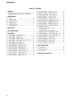
TABLE OF CONTENTS
1. GENERAL
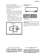
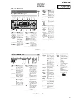
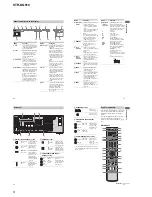
Description and location of parts (US, Canadian model) ........ 5
Description and location of parts (AEP, UK, E2 model) ......... 7
2. DISASSEMBLY
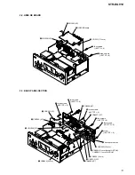
2-1. Case ................................................................................... 10
2-2. HDMI RE Board ............................................................... 11
2-3. Back Panel Section ............................................................ 11
2-4. Front Panel Section ........................................................... 12
2-5. DIGITAL Board ................................................................ 12
2-6. MAIN Board Section ........................................................ 13
2-7. STANDBY Board ............................................................. 13
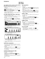
3. TEST MODE
..................................................................... 14
4. FM TUNER CHECK
....................................................... 15
5. DIAGRAMS
5-1. Block Diagram – Tuner/Audio Section – .......................... 17
5-2. Block Diagram – Digital Section – ................................... 18
5-3. Block Diagram – Video Section – ..................................... 19
5-4. Block Diagram – HDMI SW Section – ............................. 20
5-5. Block Diagram – XM Section (US, Canadian Model) – .. 21
5-6. Block Diagram – Key/Display Section – .......................... 22
5-7. Block Diagram – Power Section – .................................... 23
5-8. Printed Wiring Boards – Main Section – .......................... 25
5-9. Schematic Diagram – Main Section (1/4) – ...................... 26
5-10. Schematic Diagram – Main Section (2/4) – ...................... 27
5-11. Schematic Diagram – Main Section (3/4) – ...................... 28
5-12. Schematic Diagram – Main Section (4/4) – ...................... 29
5-13. Printed Wiring Board – Digital Section (1/2) – ................ 30
5-14. Printed Wiring Board – Digital Section (2/2) – ................ 31
5-15. Schematic Diagram – Digital Section (1/5) – ................... 32
5-16. Schematic Diagram – Digital Section (2/5) – ................... 33
5-17. Schematic Diagram – Digital Section (3/5) – ................... 34
5-18. Schematic Diagram – Digital Section (4/5) – ................... 35
5-19. Schematic Diagram – Digital Section (5/5) – ................... 36
5-20. Printed Wiring Board – Video Section (1/2) – .................. 37
5-21. Printed Wiring Boards – Video Section (2/2) – ................. 38
5-22. Schematic Diagram – Video Section (1/2) – ..................... 39
5-23. Schematic Diagram – Video Section (2/2) – ..................... 40
5-24. Printed Wiring Board – HDMI RE Section (1/2) – ........... 41
5-25. Printed Wiring Board – HDMI RE Section (2/2) – ........... 42
5-26. Schematic Diagram – HDMI RE Section (1/4) – .............. 43
5-27. Schematic Diagram – HDMI RE Section (2/4) – .............. 44
5-28. Schematic Diagram – HDMI RE Section (3/4) – .............. 45
5-29. Schematic Diagram – HDMI RE Section (4/4) – .............. 46
5-30. Printed Wiring Board
– XM Section (US, Canadian Model) – ............................ 47
5-31. Schematic Diagram
– XM Section (US, Canadian Model) – ............................ 48
5-32. Printed Wiring Board – Front Speaker Section – .............. 49
5-33. Schematic Diagram – Front Speaker Section – ................. 49
5-34. Printed Wiring Boards – DCAC, Power Key Section – .... 50
5-35. Schematic Diagram – DCAC, Power Key Section – ........ 50
5-36. Printed Wiring Board – Display Section – ........................ 51
5-37. Schematic Diagram – Display Section – ........................... 52
5-38. Printed Wiring Boards – Power Section – ......................... 53
5-39. Schematic Diagram – Power Section – ............................. 54
5-40. Printed Wiring Board – DCDC Section – ......................... 55
5-41. Schematic Diagram – DCDC Section – ............................ 55
6. EXPLODED VIEWS
6-1. Case Section ...................................................................... 74
6-2. Front Panel Section ........................................................... 75
6-3. Back Panel Section ............................................................ 76
6-4. Chassis Section ................................................................. 77
7. ELECTRICAL PARTS LIST
........................................ 78
Summary of Contents for STR-DG910
Page 105: ...105 STR DG910 MEMO ...


