background image

masterpage:Left

lename[E:\SEM_Janet\Data_DB895D\J9050665_2598514111DB895DCEL\2598514111\GB05

SND_STR-DB895D-CEL.fm]

38

GB

 model name1[STR-DB895D]

 [2-598-514-

11

(1)]

Selecting a sound field for 
music

Press MUSIC repeatedly to select the 
sound field you want.

The selected sound field appears in the display.

x

HALL

Reproduces the acoustics of a classical concert hall.

x

JAZZ (JAZZ CLUB)

Reproduces the acoustics of a jazz club.

x

CONCERT (LIVE CONCERT)

Reproduces the acoustics of a 300-seat live house. 

When the headphones are 
connected

You can select only from the following sound 
fields.

x

HP 2CH (HEADPHONE 2CH)

Outputs the sound in 2 channel (stereo). Standard 2 
channel stereo sources completely bypass the sound 
field processing and multi channel surround formats 
are downmixed to 2 channels.

x

HP DIR (HEADPHONE DIRECT)

Ouputs the analog signals without processing by 
equalizer, sound field, etc.

x

HP MULTI (HEADPHONE MULTI)

Outputs the front analog signal from MULTI CH IN 
jacks.

x

HP THEA (HEADPHONE THEATER) 

DCS

Allows you to experience a theater-like environment 
while listening through a pair of headphones. 

Note

If you connect a pair of headphones while a sound field 
is operating, the system will automatically switch to 
HEADPHONE 2CH if using a sound field selected 
with the 2CH or A.F.D. button, or to HEADPHONE 
THEATER if using a sound field selected with the 
MOVIE or MUSIC button. 

To turn off the surround effect

Press 2CH to select “2CH ST.” or press A.F.D. 
repeatedly to select “A.F.D. AUTO”.
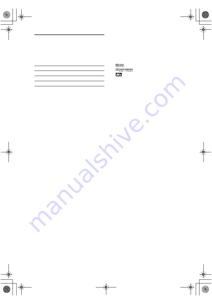
Tip

You can identify the encoding format of DVD 
software, etc. by looking at the logo on the package.

: Dolby Digital discs

: Dolby Surround encoded programs

: DTS Digital Surround encoded programs

Notes

• Sound fields do not function for the signals with a 

sampling frequency of more than 48 kHz.

• When one of the following sound fields are selected, 

no sound is output from the sub woofer if all the 
speakers are set to “LARGE” in the SPEAKER 
SETUP menu. However, the sound will be output 
from the sub woofer if the digital input signal 
contains LFE (Low Frequency Effect) signals, or if 
the front, center, or surround speakers are set to 
“SMALL”.

– HALL

– JAZZ CLUB

– LIVE CONCERT

Sound field

Display

HALL HALL

JAZZ CLUB 

JAZZ

LIVE CONCERT 

CONCERT

GB01COV_STR-DB895D-CEL.book  Page 38  Wednesday, June 15, 2005  9:28 AM

Summary of Contents for STR-DB895D

Page 1: ...net Data_DB895D J9050665_2598514111DB895DCEL 2598514111 GB01 COV_STR DB895D CEL fm masterpage Right 2005 Sony Corporation 2 598 514 11 1 DAB FM AM Receiver Operating Instructions STR DB895D GB01COV_STR DB895D CEL book Page 1 Wednesday June 15 2005 9 28 AM ...

Page 2: ...ice your household waste disposal service or the shop where you purchased the product About This Manual The instructions in this manual are for model STR DB895D Check your model number by looking at the lower right corner of the front panel In this manual the models of area code CEL is used for illustration purposes unless stated otherwise The instructions in this manual describe the controls on t...

Page 3: ...ny hiss or crackle to spoil the sound both music and data services from a single receiver this receiver does not support data services the same radio stations of the same frequency from anywhere in the country multiple programmes services from a single frequency Some service components may not match CD quality sound Notes The status of the DAB broadcast depends on your country or region It may not...

Page 4: ...RDS 29 Changing the display 31 About the indications in the display 32 Enjoying Surround Sound Using only the front speakers 34 Enjoying higher fidelity sound 35 AUTO FORMAT DIRECT Selecting a sound field 37 Selecting the surround back decoding mode 39 SURR BACK DECODING Advanced Adjustments and Settings Reassigning the component video input 41 COMPONENT VIDEO INPUT ASSIGN Switching the audio inpu...

Page 5: ...s receiver c Model equipped only with AUDIO OUT L R jacks etc d Model with component video Y PB CB B Y PR CR R Y input jacks Getting Started 1 Check how to hookup your components Component to be connected Page DVD player With digital audio outputa 7 8 With multi channel audio outputb 10 11 With analog audio output onlyc 7 8 TV monitor With component video inputd 8 or 11 With S Video or composite v...

Page 6: ...d G Monaural audio cord Black Tip Audio cord A can be torn into two monaural audio cords G H Component video cord Green Blue Red Notes Turn off the power to all components before making any connections Be sure to make connections firmly to avoid hum and noise When connecting an audio video cord be sure to match the color coded pins to the appropriate jacks on the components yellow video to yellow ...

Page 7: ...DEO IN jack on the receiver 1a Connecting components with digital audio output jacks DIGITAL DVD IN MD TAPE IN TV SAT IN MD TAPE OUT COAXIAL SA CD CD IN COMPONENT VIDEO Y PB CB B Y PR CR R Y TV SAT IN DVD IN MONITOR OUT AUDIO VIDEO SPEAKERS IN PHONO SURR FRONT OUT OUT IN VIDEO 1 OUT IN IN IN VIDEO S VIDEO VIDEO 2 DVD TV SAT SUB WOOFER CENTER SA CD CD IN IN OUT MD TAPE L R L R L R L R L R L R MULTI...

Page 8: ... from a VCR etc are upconverted on this receiver and then output to your TV depending on the status of the video signal output the image on the TV screen may appear distorted horizontally or no image may be output DIGITAL DVD IN MD TAPE IN TV SAT IN MD TAPE OUT DVD IN COAXIAL SA CD CD IN Y PB CB B Y PR CR R Y TV SAT IN DVD IN MONITOR OUT ANTENNA AUDIO VIDEO SPEAKERS IN PHONO SURR FRONT MONITOR VID...

Page 9: ...per Audio CD player connected to the SA CD CD COAXIAL IN jack on this receiver Connect the player to the analog input jacks SA CD CD IN jacks Refer to the operating instructions supplied with the Super Audio CD player DVD IN MD TAPE IN TV SAT IN MD TAPE OUT DVD IN COAXIAL SA CD CD IN Y PB CB B Y PR CR R Y TV SAT IN DVD IN ANTENNA AUDIO VIDEO SPEAKERS IN PHONO SURR FRONT MONITOR OUT OUT IN VIDEO 1 ...

Page 10: ... When you make connections to the MULTI CH IN jacks you will need to adjust the level of the speakers and sub woofer using the controls on the connected component 1b Connecting components with multi channel output jacks DIGITAL DVD IN MD TAPE IN TV SAT IN MD TAPE OUT DVD IN COAXIAL SA CD CD IN COMPONENT VIDEO Y PB CB B Y PR CR R Y TV SAT IN DVD IN MONITOR OUT ANTENNA VIDEO SPEAKERS IN PHONO SURR F...

Page 11: ...e output from the MONITOR S VIDEO OUT jack When standard video signals from a VCR etc are upconverted on this receiver and then output to your TV depending on the status of the video signal output the image on the TV screen may appear distorted horizontally or no image may be output DIGITAL DVD IN MD TAPE IN TV SAT IN MD TAPE OUT DVD IN COAXIAL SA CD CD IN Y PB CB B Y PR CR R Y TV SAT IN DVD IN MO...

Page 12: ...E IN TV SAT IN MD TAPE OUT DVD IN COAXIAL SA CD CD IN COMPONENT VIDEO Y PB CB B Y PR CR R Y TV SAT IN DVD IN MONITOR OUT ANTENNA AUDIO VIDEO SPEAKERS IN PHONO SURR FRONT MONITOR OUT OUT IN VIDEO 1 OUT IN IN IN VIDEO S VIDEO AUDIO VIDEO 2 DVD TV SAT SUB WOOFER CENTER SA CD CD IN IN OUT MD TAPE L R L R L R L R L R MULTI CH IN R L R L R L SURR FRONT B FRONT A OPTICAL DAB COAXIAL ASSIGNABLE SIGNAL GRO...

Page 13: ...signals from a VCR etc are upconverted on this receiver and then output to your TV depending on the status of the video signal output the image on the TV screen may appear distorted horizontally or no image may be output DIGITAL DVD IN MD TAPE IN TV SAT IN MD TAPE OUT DVD IN COAXIAL SA CD CD IN Y PB CB B Y PR CR R Y TV SAT IN DVD IN MONITOR OUT ANTENNA AUDIO VIDEO IN PHONO SURR FRONT MONITOR OUT O...

Page 14: ...upplied DAB wire antenna only temporarily until you install a DAB outdoor antenna Do not use the U SIGNAL GROUND terminal for grounding the receiver 2 Connecting the antennas DIGITAL DVD IN MD TAPE IN TV SAT IN MD TAPE OUT COAXIAL SA CD CD IN COMPONENT VIDEO Y PB CB B Y PR CR R Y TV SAT IN DVD IN MONITOR OUT ANTENNA AUDIO VIDEO SPEAKERS IN PHONO SURR FRONT MONITOR OUT OUT IN VIDEO 1 OUT IN IN IN V...

Page 15: ...nect one additional surround back speaker 6 1 channel or two surround back speakers 7 1 channel see Selecting the surround back decoding mode on page 39 Example of 7 1 channel speaker system configuration Tips When you connect 6 1 channel speaker system place the surround back speaker behind the listening position see When placing only one surround back speaker illustration on page 21 Since the su...

Page 16: ...rmation is often on the back of the speaker Alternatively you may connect speakers with nominal impedances between 4 and 8 ohms to any or all of the speaker terminals However be sure to set the IMPEDANCE SELECTOR to 4Ω if you connect even one speaker with a nominal impedance between 4 and 8 ohms If you connect speakers to both the SPEAKERS FRONT A and B terminals be sure to set the IMPEDANCE SELEC...

Page 17: ...button For details see Selecting the speaker system page 49 2 If you connect only one surround back speaker connect it to the SPEAKERS SURR BACK L terminal 3 Models of area code CEL only SUB WOOFER R L R L R L R L FRONT B CENTER AC IN FRONT A AUDIO OUT IMPEDANCE SELECTOR 4 8 E e A A E e A E e A E e SPEAKERS FRONT B1 IMPEDANCE SELECTOR3 E e A E e A INPUT AUDIO IN B E e A SURR BACK SPEAKERS SURR Sur...

Page 18: ...ver for the operation 1 Press 1 to turn off the receiver 2 Hold down 1 for 5 seconds PUSH and ENTER appears in the display alternatingly 3 Press MEMORY ENTER CLEARING appears in the display for a while then CLEARED appears The following are reset to their factory settings All settings in the SPEAKER SETUP LEVEL EQUALIZER CUSTOMIZE and TUNER menus The sound field memorized for each input and preset...

Page 19: ...M SET x SP PAT X X Speaker setup pattern When EASY SET is selected you can select the speaker setup pattern Turn to select the speaker setup pattern and press MEMORY ENTER to enter the selection Check your speaker pattern using the supplied Easy Setup Guide x S W XXX Sub woofer selection YES If you connect a sub woofer select YES NO If you did not connect a sub woofer select NO The front speakers ...

Page 20: ...mixed digitally DIGITAL DOWNMIX Note When using MULTI CH IN sources the sound of the center channel is output from the front speakers if you select either NO or MIX x XXXXX Surround speakers size LARGE If you connect large speakers that will effectively reproduce bass frequencies select LARGE Normally select LARGE However if the front speakers are set to SMALL you cannot set the surround speakers ...

Page 21: ...on set the distance to the closest speaker When placing only one surround back speaker When placing two surround back speakers The angle E should be the same x DIST X X m Center speaker distance Initial setting 3 0 m Lets you set the distance from your listening position to the center speaker Center speaker distance should be set from a distance equal to the front speaker distance A to a distance ...

Page 22: ... EXP page 44 This enables advanced setups including Distance unit Surround speaker position Surround speaker height Speaker crossover frequency For details on how to set the items see page 45 Adjust the speaker levels and balance while listening the test tone from your listening position Use the remote for the operation Tip The receiver employs a test tone with a frequency centered at 800 Hz 1 Pre...

Page 23: ...st their balance and level Set MENU XXX in the CUSTOMIZE menu to MENU EXP page 44 Then select the two speakers you want to adjust using P NOISE or P AUDIO in the LEVEL menu page 46 Notes The test tone cannot be used when the ANALOG DIRECT or MULTI CH IN function is used Although these adjustments can also be made via the front panel using the LEVEL menu when the test tone is output the receiver sw...

Page 24: ...rn down the volume before you turn off the receiver To mute the sound Press MUTING on the remote The muting function will be canceled when you do the following Press MUTING on the remote again Turn the power off Increase the volume To use the headphones Connect the headphones to the PHONES jack When the headphones are connected speaker output is automatically canceled and SP A and SP B do not ligh...

Page 25: ...roadcasts through the built in tuner Before operation make sure you have connected the FM and AM antennas to the receiver see page 14 Tip The tuning scale differs depending on the area code as shown in the following table For details on area codes see page 2 Automatic tuning If you do not know the frequency of the station you want you can let the receiver scan all available stations in your area 1...

Page 26: ... To avoid damaging your speakers make sure that you turn down the volume before you use the AUTOBETICAL function 1 Press 1 to turn off the receiver 2 Hold down MEMORY ENTER and press 1 to turn the receiver back on AUTO BETICAL SELECT appears in the display and the receiver scans and stores all the FM and FM RDS stations in the broadcast area For RDS stations the tuner first checks for stations bro...

Page 27: ...roll across the display In this case do the DAB INITIAL SCAN procedure page 27 Do not press any button on the receiver or supplied remote during DAB INITIAL SCAN except 1 If you move to another area repeat this procedure to store stations in your new area This procedure does not create any presets This procedure clears all previously stored presets For details on presets see Presetting radio stati...

Page 28: ...ly to select a memory page A B or C for FM AM bands and D E or F for DAB stations and then press the numeric buttons to select a preset number 5 Press MEMORY ENTER again The station is stored to the selected preset number If the MEMORY indication turns off before you press MEMORY ENTER start again from step 3 6 Repeat steps 2 to 5 to preset another station Notes When you preset a DAB or RDS statio...

Page 29: ...display RDS information Notes RDS is operable only for FM stations Not all FM stations provide RDS service nor do they provide the same types of services If you are not familiar with the RDS services in your area check with your local radio stations for details Receiving RDS broadcasts Simply select a station on the FM band using automatic tuning page 25 direct tuning page 26 or preset tuning page...

Page 30: ...y VARIED Other types of programs such as celebrity interviews panel games and comedy POP M Popular music programs ROCK M Rock music programs EASY M Easy Listening LIGHT M Instrumental vocal and choral music CLASSICS Performances of major orchestras chamber music opera etc OTHER M Music that does not fit into any categories above such as Rhythm Blues and Reggae WEATHER Weather information FINANCE S...

Page 31: ... Time indication in 24 hour system c t Channel label t Audio Infod t Signal Qualitye t Sound field currently applied t Volume level a Index name appears only when you have assigned one to the input or preset station page 47 Index name does not appear when only blank spaces have been entered or it is the same as the input name b During RDS reception only page 29 c Time information appearing in the ...

Page 32: ...d surround channel signals PRO LOGIC II lights up when the Pro Logic II Movie Music Game decoder is activated PRO LOGIC IIx lights up when the Pro Logic IIx Movie Music Game decoder is activated However these indicators do not light up if both the center and surround speakers are set to NO and you select a sound field using the A F D button Note Dolby Pro Logic IIx decoding does not function for D...

Page 33: ... to COAX IN page 41 N OPT Lights up when the source signal is a digital signal being input through the OPTICAL terminal or when INPUT MODE is set to OPT IN page 41 O SLEEP Lights up when sleep timer is activated P Playback channel indicators The letters L C R etc indicate the channels being played back The boxes around the letters vary to show how the receiver downmixes the source sound based on t...

Page 34: ...reo sources using the front left right speakers and a sub woofer set A F D mode to A F D AUTO Listening to analog audio ANALOG DIRECT You can listen to the sound without adjusting the equalizer and surround effect This function enables you to enjoy high quality analog sources Also see D PWR XXX on page 45 When using this function only the volume and front speaker balance can be adjusted 1 Turn INP...

Page 35: ...e a low frequency signal for output to the sub woofer Press A F D repeatedly to select A F D AUTO The receiver automatically detects the type of audio signal being input and performs the proper decoding if necessary Tip In most cases A F D AUTO provides the most appropriate decoding You may want to use SURR BACK DECODING page 39 to match the input stream to the mode you prefer Enjoying higher fide...

Page 36: ...Pro Logic II Game mode decoding This setting is ideal for video game softwares x PLIIX MV PRO LOGIC IIx MOVIE Performs Dolby Pro Logic IIx Movie mode decoding This setting expands Dolby Pro Logic II Movie or Dolby Digital 5 1 to discrete 7 1 movie channels x PLIIX MS PRO LOGIC IIx MUSIC Performs Dolby Pro Logic IIx Music mode decoding This setting shares hard back effects across all surround speak...

Page 37: ...cience fiction or action movies with lots of sound effects x C ST EX C CINEMA STUDIO EX C D CS Reproduces the sound characteristics of the Sony Pictures Entertainment scoring stage This mode is ideal for watching musicals or films where orchestra music is featured in the soundtrack x V M DIM VIRTUAL MULTI DIMENSION DC S Creates 5 sets of virtual speakers from a single pair of actual surround speak...

Page 38: ...like environment while listening through a pair of headphones Note If you connect a pair of headphones while a sound field is operating the system will automatically switch to HEADPHONE 2CH if using a sound field selected with the 2CH or A F D button or to HEADPHONE THEATER if using a sound field selected with the MOVIE or MUSIC button To turn off the surround effect Press 2CH to select 2CH ST or ...

Page 39: ...ess SURR BACK DECODING repeatedly to select the surround back decoding mode SB XXXX appears in the display For details see How to select the surround back decoding mode on page 40 Tip You can select the surround back decoding mode using SB XXXX in the CUSTOMIZE menu page 44 Notes You can select the surround back decoding mode only when you use a sound field selected with the A F D button except fo...

Page 40: ... returning those signals to 6 1 discrete channels Discrete 6 1 channel signals are DVD specific signals not used in movie theaters e When two surround back speakers are connected the output channel will be 7 1 channels Note There may be no sound from the surround back speaker in Dolby Digital EX mode Some discs have no Dolby Digital EX flag even though the packages have Dolby Digital EX logos In t...

Page 41: ... Press INPUT MODE repeatedly to select the audio input mode The selected audio input mode appears in the display Audio input modes x AUTO IN Gives priority to digital signals when there are both digital and analog connections If there are no digital signals analog is selected x COAX IN Specifies the digital audio signals input to the DIGITAL COAXIAL input jack x OPT IN Specifies the digital audio ...

Page 42: ...to FIX XXX you can select which speaker will output the test tone x BAL L R XXX Front speaker balance Initial setting 0 BALANCE Lets you adjust the balance between front left and right speakers You can adjust in the range of BAL L 1 to 16 BALANCE 0 BAL R 1 to 16 in 33 steps x CTR XXX X dB Center speaker level x SUR L XXX X dB Surround speaker left level x SUR R XXX X dB Surround speaker right leve...

Page 43: ...tedly to select E Q 3 Turn MENU to select the parameter you want to adjust For details see EQUALIZER menu parameters below 4 While monitoring the sound turn to select the setting you want The setting is entered automatically 5 Repeat steps 3 and 4 to adjust the other items Note You cannot adjust the equalizer when the receiver is decoding signals with a sampling frequency of more than 48 kHz or wh...

Page 44: ...O x SB XXXX Surround back decoding mode You can also press SURR BACK DECODING to select the surround back decoding mode page 39 For details on each decoding mode see page 40 OFF AUTO ON Note This parameter is valid only when you use a sound field selected with the A F D button except for Dolby Pro Logic IIx mode page 35 x S F XXXX Sound field link LINK Lets you apply the last selected sound field ...

Page 45: ... Component video input assignment Lets you reassign the component video input to another visual input For details see Reassigning the component video input on page 41 x DIMMER Brightness of the display Lets you adjust the brightness of the display in 3 steps x NAME IN Naming preset stations and inputs Lets you set the name of preset stations and inputs selected with INPUT SELECTOR For details see ...

Page 46: ... the height of your surround speakers corresponds to section A HIGH Select if the height of your surround speakers corresponds to section B This setup item is not available when the surround speaker size parameter is set to NO x SP XXX Hz Speaker crossover frequency Initial setting 100 Hz Lets you adjust the bass crossover frequency of speakers set to SMALL in the SPEAKER SETUP menu You can adjust...

Page 47: ...select NAME IN 4 Press MEMORY ENTER The cursor flashes and you can select a character Follow the procedure of To create an index name To create an index name 1 Use MENU and to create an index name Turn to select a character then turn MENU to move the cursor to the next position Tips You can select the character type as follows by turning Alphabet upper case t Numbers t Symbols To enter a blank spa...

Page 48: ...e command mode of the receiver and the remote is different you cannot use the remote to operate the receiver You can set the receiver to turn off automatically at a specified time Use the remote for the operation 1 Press ALT to light up the button 2 Press SLEEP repeatedly while the power is on Each time you press SLEEP the display changes cyclically as follows 2 00 00 t 1 30 00 t 1 00 00 t 0 30 00...

Page 49: ...l if necessary 4 Start recording on the recording deck then start playback on the playback component Notes You cannot record a digital audio signal using a component connected to the analog MD TAPE OUT jacks To record a digital audio signal connect a digital component to the DIGITAL OPTICAL MD TAPE OUT jack Sound adjustments do not affect the signal output from the MD TAPE OUT jacks The analog aud...

Page 50: ... 2 for recording 4 Start recording on the recording VCR then start playing the video tape or DVD you want to record Notes You cannot record a digital audio signal using a component connected to the analog VIDEO 1 AUDIO OUT or VIDEO 2 AUDIO OUT jacks Make sure to make both digital and analog connections to the TV SAT and DVD inputs Analog recording is not possible if you make only digital connectio...

Page 51: ...tion If you do not use the remote for an extended period of time remove the batteries to avoid possible damage from battery leakage and corrosion The H TV VOL TV CH and MASTER VOL buttons have a tactile dot Use the tactile dot as a reference when operating the receiver and other audio video components Operations Using the Remote RM AAP002 Before you use your remote Remote button description H X m ...

Page 52: ...layer DVD player MD deck DAT deck Blu ray disc recorder Hard disc recorder PSX Turns the audio and video components on or off Remote Button Operations Function CLEAR wj Satellite tuner CD player DVD player Blu ray disc recorder PSX Clears a mistake when you press the incorrect numeric buttons or returns to continuous playback etc DIMMER w Receiver Adjusts the brightness of the display DIRECT wl Re...

Page 53: ...e previous menu Satellite tuner Exits the menu RM SET UP ej Remote To set up the remote SA CD CD 5 Receiver To listen to Super Audio CD or compact disc Remote Button Operations Function SB DECODING q Receiver Selects the surround back decoding modes SEARCH MODE qf DVD player Selectssearchingmode Press to select the unit for search track index etc SHIFT wj Receiver Selects a memory page for presett...

Page 54: ...wk CD player VCD player LD player MD deck Tape deck Selects track numbers over 10 TV VCR Satellite tuner Blu ray disc recorder Hard disc recorder PSX Selects channel numbers over 10 or selects number 11 key Remote Button Operations Function wk VCR CD player VCD player DVD player LD player MD deck DAT deck Tape deck Blu ray disc recorder Hard disc recorder PSX Skips tracks m M wj CD player VCD play...

Page 55: ...s an example only Therefore depending on the component the above operation may not be possible or may operate differently than described When you press input buttons VIDEO1 VIDEO2 VIDEO3 TV SAT or DVD the input mode of the TV might not switch to the corresponding input mode that you want In this case press TV VIDEO button to switch the input mode of the TV Remote Button Operations Function x qg VC...

Page 56: ...mponents as part of your system Furthermore you can also program the remote for Sony components that the remote is unable to control Note that the remote can only control components that accept infrared wireless control signals 1 Press AV 1 while holding down RM SET UP The indicator lights up 2 Press the input button including TV 1 for the component you want to control For example if you are going...

Page 57: ...umbers entered are valid To clear the memory of the remote To clear all programmed signals do the following to reset the remote to factory settings Press 1 AV 1 and MASTER VOL at the same time The indicator flashes 3 times then goes off The numeric codes corresponding to the component and the maker of the component Use the numeric codes in the tables below to control non Sony components and also S...

Page 58: ... PIONEER 213 214 TECHNICS 215 216 YAMAHA 217 218 Maker Code s SONY 601 602 603 PIONEER 606 Maker Code s SONY 605 Maker Code s SONY 701 702 703 704 705 706 AIWA 710 750 757 758 AKAI 707 708 709 759 BLAUPUNKT 740 EMERSON 711 712 713 714 715 716 750 FISHER 717 718 719 720 GENERAL ELECTRIC 721 722 730 GOLDSTAR 723 753 GRUNDIG 724 HITACHI 722 725 729 741 ITT NOKIA 717 JVC 726 727 728 736 MAGNAVOX 730 7...

Page 59: ... 517 534 HITACHI 513 514 515 544 ITT NOKIA 521 522 JVC 516 MAGNAVOX 503 518 544 MITSUBISHI MGA 503 519 544 NEC 503 520 544 PANASONIC 509 524 PHILIPS 515 518 PIONEER 509 525 526 RCA PROSCAN 510 527 529 544 SAMSUNG 503 515 531 532 533 534 544 SANYO 508 545 547 SHARP 535 TELEFUNKEN 523 537 547 THOMSON 530 537 547 TOSHIBA 535 541 ZENITH 542 543 Maker Code s SONY 801 802 803 804 JERROLD G I 806 807 808...

Page 60: ...alfunction If you continuously use this receiver at a large volume the cabinet temperature of the top side and bottom rises considerably To avoid burning yourself do not touch the cabinet On placement Place the receiver in a location with adequate ventilation to prevent heat buildup and prolong the life of the receiver Do not place the receiver near heat sources or in a place subject to direct sun...

Page 61: ...INPUT MODE is not set to COAX IN or OPT IN page 41 Check that you have not selected MULTI CH IN function There is no sound from digital sources from COAXIAL or OPTICAL input jack Check that the INPUT MODE is not set to ANALOG page 41 Check that the INPUT MODE is not set to COAX IN for the sources from OPTICAL input jack or set to OPT IN for the sources from COAXIAL input jack Check that you have n...

Page 62: ... you have moved to another area some services frequencies may have changed and you may not be able to tune into your usual broadcast Perform the DAB INITIAL SCAN procedure to re register the contents of broadcast Performing this procedure clears all previously stored presets page 27 The FM reception is poor Use a 75 ohm coaxial cable not supplied to connect the receiver to an outdoor FM antenna as...

Page 63: ...the AUX and MULTI CH buttons before you can use the buttons to control your audio video equipment For details refer Programming the remote on page 56 To activate the buttons with orange printing press ALT first before pressing the buttons Before you use the V v B b button for receiver operation press MAIN MENU To operate other components press TOP MENU GUIDE or AV MENU after pressing the function ...

Page 64: ...rce there may be no sound output Frequency response Inputs Analog 3 INPUT SHORT 4 Weighted network input level Inputs Digital Outputs Analog Outputs Digital Equalizer Specifications Area code Power requirements CEL CEK 230 V AC 50 Hz PHONO RIAA equalization curve 0 5 dB MULTI CH IN SA CD CD MD TAPE DVD TV SAT VIDEO 1 2 3 10 Hz 100 kHz 0 5 2 dB when ANALOG DIRECT is selected PHONO Sensitivity 2 5 m...

Page 65: ...z 15 kHz 0 5 2 dB Selectivity 60 dB at 400 kHz AM tuner section Tuning range With 9 kHz tuning scale 531 1 602 kHz Antenna Loop antenna Intermediate frequency 450 kHz Usable sensitivity 50 dB m at 1 000 kHz or 999 kHz S N 54 dB at 50 mV m Harmonic distortion 0 5 50 mV m 400 Hz Selectivity At 9 kHz 35 dB Video section Inputs Outputs Video 1 Vp p 75 ohms S video Y 1 Vp p 75 ohms C 0 286 Vp p 75 ohms...

Page 66: ...40MHz 7B 225 648MHz 12B 192 352MHz 7C 227 360MHz 12C 194 064MHz 7D 229 072MHz 12D 195 936MHz 8A 230 784MHz 13A 197 648MHz 8B 232 496MHz 13B 199 360MHz 8C 234 208MHz 13C 201 072MHz 8D 235 776MHz 13D 202 928MHz 9A 237 488MHz 13E 204 640MHz 9B 239 200MHz 13F 206 352MHz 9C 208 064MHz 9D Frequency Label Frequency Label 1452 960MHz LA 1473 504MHz LM 1454 672MHz LB 1475 216MHz LN 1456 384MHz LC 1476 928M...

Page 67: ...8 62 PHONES jack wg 24 61 PRESET TUNING wa 28 PUSH wf 67 SPEAKERS OFF A B A B wh 17 49 61 SURR BACK DECODING ql 39 TUNING w 25 VIDEO 3 INPUT jacks wd 7 8 2CH qk 34 38 43 6 19 42 43 47 1 power 2 18 19 26 43 List of button locations and reference pages How to use this page Use this page to find the location of buttons that are mentioned in the text Illustration number r DISPLAY 9 29 31 62 R R Name o...

Page 68: ...Dual Mono 45 Dubbing See Recording E Editing See Recording EQUALIZER menu 43 I Indexing See Naming L Labeling See Naming LEVEL menu 42 46 N Naming 47 P Preset stations how to 28 how to tune 28 R RDS 29 Recording on a video tape 50 on an audio tape or MD 49 Remote commander 51 59 S Selecting component 24 sound field 37 38 speaker system 49 Sleep Timer 48 Sound field customizing 42 pre programmed 37...

Reviews: