– 59 –
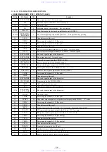
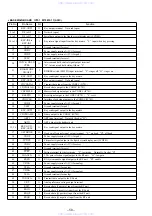
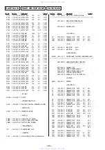
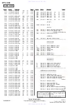
Pin No.
Pin Name
I/O
Function
55
NC
—
Not used (open)
56
IBIAS
I
Analog bias input terminal
57
AGND
—
Analog ground terminal
58
POWERDOWN
I
Battery voltage detection input terminal “L”: power down
59
AFC (BEEP)
O
Beep tone signal output terminal
60
AGC
O
Auto gain control signal output to the RF unit
61
MT-CLK
O
Caller-ID clock signal (1.2 kHz) output to the MT88E43 (IC150)
62
PARKP
I
Charge detection input terminal “L”: charge on
63
VDDC
—
Power supply terminal (+5V) (for core)
64
VSSP
—
Ground terminal (for pad)
65
SYNDATA
O
Synthesizer data output to the RF unit
66
SYNTH5MCLK
O
Synthesizer reference oscillator output to the RF unit (9.62 MHz)
67
LCD REG-SET
O
Register selection signal output to the liquid crystal display unit (LCD801)
“L”: instruction register, “H”: data register
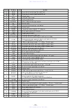
68
LINE-LED
O
LED drive signal output of the LINE LED (D1002) “L”: LED on
69
MT-INT
I
Caller-ID interrupt input from the MT88E43 (IC150) “L” active
70
MT-DATA
I
Caller-ID data input from the MT88E43 (IC150)
71
SYNCLK
O
Synthesizer clock signal output to the RF unit
72
SYNSTB
O
Synthesizer strobe signal output to the RF unit
73
VDDP
—
Power supply terminal (+5V) (for pad)
74
VSSP
—
Ground terminal (for pad)
75
SYNEN
O
Synthesizer power control signal output to the RF unit “H”: enable
76
NVDI
I/O
Two-way data bus with the EEPROM (IC951)
77
NVDO
O
Clock signal output to the EEPROM (IC951)
78
LCD-R/W
O
Data read/write selection signal output to the liquid crystal display unit (LCD801)
“L”: data write, “H”: data read
79
TXEN
O
TX system enable signal output to the RF unit “H”: enable
80
TXPWR1
O
PA power selection signal output to the RF unit
81
RINGIN
I
Detection signal input of the ringer coming “L”: ringer coming
82
TXRXSEL
O
TX/RX selection signal output to the RF unit “L”: RX, “H”: TX
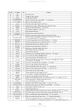
I
Battery charge monitor input terminal
I
Setting terminal for the base/handset selection
“L”: base unit, “H”: handset unit (fixed at “L” in this set)
O
PA power selection signal output to the RF unit
O
Enable control signal output to the voice speakerphone (IC103) “L”: enable, “H”: CD
O
Quick/normal charge selection signal output terminal
“H”: normal charge, “L”: quick charge
I
Dial mode switch (SW951) input terminal “L”: pulse, “H”: tone
O
LED drive signal output of the NEW CALL LED (D809) “L”: LED on
90
VDDC
—
Power supply terminal (+5V) (for core)
91
VSSC
—
Ground terminal (for core)
92
SP-MUT
O
Speaker muting on/off control signal output to the power amplifier (IC104) “H”: muting
93
MT-FSK-EN
O
Caller-ID frequency shift keying enable signal output to the MT88E43 (IC150)
94
BRANCH-DET
I
Reserve cancellation detect signal input terminal “H”: cancel status
95
DIALMUT
O
Reception muting during dial transmission “H”: during dial transmission
96
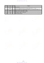
RESETI
I
System reset signal input from the reset signal generator (IC602) “L”: reset
For several hundreds msec. after the power supply rises, “L” is input, then it changes to “H”
www. xiaoyu163. com
QQ 376315150
9
9
2
8
9
4
2
9
8
TEL 13942296513
9
9
2
8
9
4
2
9
8
0
5
1
5
1
3
6
7
3
Q
Q
TEL 13942296513 QQ 376315150 892498299
TEL 13942296513 QQ 376315150 892498299

