background image

SLV-ED115/ED215/ED313/ED515/ED616/ED815/ED817/ED818/ED915/ED919/EZ111/EZ212/EZ414/EZ715/EZ717

(SEE PAGE 4-7,4-11, 4-15)

EXCEPT ED115/ED215/
ED313/EZ111/EZ212   

ED815/ED817/ED818/
ED915/ED919/EZ715/
EZ717

3-1

3-2

SECTION 3

BLOCK DIAGRAMS

3-1. OVERALL BLOCK DIAGRAM

Summary of Contents for RMT-V309

Page 1: ...D817 ED818 ED915 ED919 EZ111 EZ212 EZ414 EZ715 and EZ717 contained in this service manual are indicated when these models are common to all their corresponding models as given below ED115 Abbreviated model name All model names SLV ED215 ED313 ED515PS ED515 ED313ME ED313MJ ED313SG RMT V309 V311 V311A V311B V311C V311D V311E SLV ED115 ED215 ED313 ED515 ED616 ED815 ED817 ED818 ED915 ED919 EZ111 EZ212...

Page 2: ... AS28 to AS69 CATV S01 to S05 S1 to S41 EZ111 EZ212 EZ414 EZ715NZ COUNTRY is set to NZ EZ717NZ VHF NZ1 to NZ11 UHF E21 to E69 CATV S01 to S05 S1 to S41 RF output signal ED115 ED215 ED313 ED515 ED616 ED815 ED817 ED818 ED915 ED919 EZ715NZ EZ717NZ UHF channels 21 to 69 EZ111 EZ212 EZ414 EZ715AS EZ717AS UHF channels 28 to 69 Aerial out 75 ohm asymmetrical aerial socket Inputs and outputs LINE 1 IN VID...

Page 3: ... 2pin 2pin 3pin 3pin 3pin 3pin 3pin 3pin 3pin B Y B Y B Y B B Y B B Y R W Y R W Y R W Y R W Y R W Y RCA FRONT LINE INPUT 3pin 3pin 3pin 3pin Y B B Y B B Y W R Y W R MODULATOR SYSTEM G K I G K I G K I G K I G K I G K I G K I G K I G K I G K I M REMOTE COMMANDER RMT V311 V311 V311 V311 V311B V311 V311A V311B V311A V311C SLV EZ111 EZ212 EZ414 EZ715 EZ717 FEATURE AZ AZ AZ AS NZ AS NZ HEAD CH 2 2 2 2 4...

Page 4: ... Video Block Interface MA 402 BOARD IC101 5 1 5 2 System Control Servo Peripheral Circuit Interface MA 402 BOARD IC101 5 1 5 3 System Control Mechanism Block Interface MA 402 BOARD IC101 5 2 5 4 System Control Audio Block Interface MA 402 BOARD IC101 5 3 5 5 Servo System Control OSD Microprocessor Pin Function MA 402 BOARD IC101 5 4 5 6 NICAM Processor Pin Function NK 11 BOARD IC1 5 5E 5 7 ZWEITON...

Page 5: ...k Ass y Page 14 Ground Shaft Ass y Page 13 Mechanism Deck Page 2 3 FL Complete Ass y Page 13 Drum Ass y Page 13 Rear Panel Page 2 2 Rubber Belt Page 15 Rubber Belt Page 15 Slider Page 26 Loading Gear T S Page 28 Retainer Plate Page 22 Rubber Belt Page 15 Capstan Motor Page 15 FL Slider Block Ass y Page 22 Pully Gear Ass y Page 29 Cam Motor Retainer Page 31 Cam Gear Page 23 Cam Motor Page 31 Reel D...

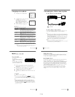
Page 6: ...es and VCR pictures on your TV In addition if your TV has audio video A V input jacks we recommend you connect the VCR to your TV using an audio video cable to get a better picture and sound Connecting the aerial OUT IN AERIAL IN OUT AERIAL 7 Getting Started Getting Started Additional connections Note To play a tape in stereo you must use either one of the connections shown below To a TV that has ...

Page 7: ...automatically set them manually If there are any unwanted channels among the preset ones you can disable the channels If you live in the area where various TV systems coexist and have channels that do not match the TV system you selected in automatic presetting reset the TV system for those channels see Resetting the TV system on page 15 If the channels do not match the TV system the sound may be ...

Page 8: ...tting Started Getting Started Disabling unwanted programme positions After presetting channels you can disable unused programme positions The disabled positions will be skipped later when you press the PROG buttons 1 In step 5 on page 14 press programme number button 0 twice to display the number 0 beside CHANNEL SET 2 Press OK Resetting the TV system only for areas where various TV systems coexis...

Page 9: ... E41 E42 E43 E44 E45 E46 E47 E48 E49 E50 E51 E52 E53 E54 E55 E56 E57 E58 E59 E60 E61 E62 E63 33 34 35 36 37 38 39 40 41 42 43 44 45 46 47 48 49 50 51 52 53 54 55 56 57 58 59 60 61 62 63 64 65 66 67 68 Step 5 Presetting channels continued 19 Getting Started Getting Started TV system Country Channel number in the CHANNEL SET column 64 65 66 67 68 69 70 C1 C2 C3 C4 C5 C6 C7 C8 C9 C10 C11 C12 C13 C14 ...

Page 10: ...54 39 40 W 55 41 W 56 42 W 57 W 58 43 44 W 59 45 W 60 46 W 61 W 62 47 48 W 63 49 W 64 50 W 65 W 66 51 52 W 67 53 W 68 54 W 69 W 70 55 56 W 71 57 W 72 58 W 73 W 74 59 60 W 75 61 W 76 62 W 77 W 78 63 64 W 79 65 W 80 66 W 81 W 82 67 68 W 83 69 W 84 J28 J29 J30 J31 J32 J33 J34 J35 J36 J37 J38 J39 J40 J41 J42 J43 J44 J45 J46 J47 J48 J49 J50 J51 J52 J53 J54 J55 J56 J57 J58 J59 J60 J61 J62 Step 5 Presett...

Page 11: ...n on the satellite tuner 2 Press MENU then select TUNER PRESET and press OK 3 Press PROG to select a programme position you want to use for watching a satellite channel 4 Select CHANNEL SET then press to tune the VCR to the satellite tuner The channel number displayed in the CHANNEL SET column is used for receiving all satellite broadcasts from the satellite tuner 5 Press PROG to select another pr...

Page 12: ... video channel CLEAR OK M m MENU Step 7 Changing disabling programme positions continued 1 2 3 4 5 6 7 8 9 0 SET UP CH AND G CODE GUIDE CH 1 2 3 4 5 9 12 56 27 3 SELECT MOVE PROG 12 16 2 6 ERASE PROG CLEAR PROG CH SET UP CH AND G CODE GUIDE CH 1 2 3 4 5 9 12 56 27 3 SELECT MOVE PROG 12 16 2 6 ERASE PROG CLEAR PROG CH OK PLAY MENU OK PLAY 31 Getting Started Getting Started 3 Press CLEAR The selecte...

Page 13: ...stem of your TV For details see page 65 Set NTSC PB to ON PAL TV 4 43 3 58 3 Press H PLAY When the tape reaches the end it will rewind automatically continued OK PLAY Additional tasks Basic Operations 36 To use the time counter At the point on the tape that you want to find later press CLEAR The counter in the display window resets to 0 00 00 Search for the point afterwards by referring to the cou...

Page 14: ...video source from the LINE 1 IN or LINE 2 IN jacks Press INPUT SELECT or PROG to display L1 or L2 in the display window The display appears on the TV screen indicating information about the tape but the information will not be recorded on the tape If you do not want to watch TV while recording you can turn off the TV You can have the VCR stop recording automatically after starting at a specified t...

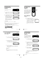
Page 15: ...P mode Change the time by one minute in START STOP mode Select the programme Change the hour minute by one hour minute in CLOCK mode Do this on the VCR Push the EASY TIMER knob Turn the EASY TIMER knob or hold PROGRAM down Press PROGRAM Turn the EASY TIMER knob or press PROGRAM Turn the EASY TIMER knob or press PROGRAM Do this on the remote commander Press EASY TIMER Hold PROG down Press PROG Pres...

Page 16: ...rd If you make a mistake press CLEAR and re enter the correct number 3 Press REC SPEED to select SP or LP 4 Select ONCE DAILY or WEEKLY by using then press OK The date start and stop times programme position and tape speed appear on the TV screen If the information is not correct press CLEAR to cancel the setting 5 To enter another setting repeat steps 1 to 4 6 Press 1 to turn off the VCR The t in...

Page 17: ...ramme If you record a programme using the Easy Timer function you can easily find the beginning of the recording with the SEARCH MODE function The SEARCH MODE indicator flashes when the VCR finishes making an Easy Timer recording Push the EASY TIMER knob The VCR turns on rewinds to the beginning of the recorded programme and starts playback automatically The SEARCH MODE indicator turns off Tip You...

Page 18: ...ng and the index number on the TV screen counts down to zero Playback starts from the point about five seconds ahead of the specified index mark SEARCH INDEX 8 INDEX SEARCH 55 Search Operations Using the SEARCH MODE button and EASY TIMER knob on the VCR 1 Press SEARCH MODE on the VCR repeatedly until INDEX appears in the display window the SEARCH MODE indicator lights up 2 Turn the EASY TIMER knob...

Page 19: ...in the display window 2 Press z REC repeatedly to set the duration Each press advances the time in increments of 30 minutes The tape counter decreases minute by minute to 0 00 then the VCR stops recording and turns off automatically To extend the duration Press z REC repeatedly to set to the new duration To cancel the duration Press z REC repeatedly until the t indicator turns off and the VCR retu...

Page 20: ...Usually mixed left right channels Stereo Bilingual Usually main sound On screen display STEREO L CH R CH No indicator Recording stereo and bilingual programmes continued 63 Additional Operations Adjusting the picture Adjusting the tracking Although the VCR automatically adjusts the tracking when playing a tape the indicator flashes in the display window then turns off distortion may occur if the t...

Page 21: ...t the plugs to the jacks of the same colour If you connect this VCR to both the LINE IN and LINE OUT jacks of the other VCR select the input correctly to prevent a humming noise This VCR Recorder VMC 810HG audio video cable not supplied LINE 2 IN Other VCR Player LINE OUT TV Signal flow 67 Additional Operations Operation when recording on this VCR Before you start editing Turn on your TV and set i...

Page 22: ...NE 1 IN AUDIO R L VIDEO jacks 66 3 AERIAL IN connector 6 4 AERIAL OUT connector 6 5 LINE OUT AUDIO R L VIDEO jacks 7 Index to parts and controls continued STEREO NICAM SP EP LP STOP APC START CLOCK NTSC PAL 8 APC Adaptive Picture Control indicator 64 9 Tracking indicator 63 0 Colour system indicator 35 qa Time counter clock line programme TV system indicator 8 36 37 42 67 qs Tape recording indicat...

Page 23: ... Follow the disassembly procedure in the numerical order given 9 Earth Plate 1 Five screws B2 6 8 2 DM 98 board 3 Flat Cable FDM 010 4 DI 81 board 6 FJ 31 board 7 Flat Cable FDI 002 Two screws B2 6 8 0 Two screws B2 6 8 8 5 Flat Cable FDI 002 2 2 DM 98 BOARD DI 81 BOARD FJ 31 BOARD SLV ED115 ED215 ED313 ED515 ED616 ED815 ED817 ED818 ED915 ED919 EZ111 EZ212 EZ414 EZ715 EZ717 2 1 CASE FRONT PANEL BL...

Page 24: ...2 2 2 MA 402 board with mechanism deck 1 Six screws Sumitite B3 BV Hooks Hooks Hooks Hooks 2 Rear panel Engaged by the seven hooks 1 POWER code stopper 2 4 MA 402 BOARD 2 3 REAR PANEL ...

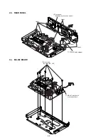
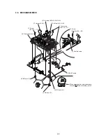
Page 25: ...crews BVTP 3 12 9 Screw BVTP 3 12 2 Screw Sumitite B3 BV qs Mechanism deck 1 Flexible cable 5 Harness FE 127 3 Flat Cable FAC 009 4 Flat cable FMD 022 FMD 023 CN202 CN331 Note When mounting the mechanism deck first align mark on the rotary switch 2 5 MECHANISM DECK ...

Page 26: ... Drum assembly M901 DZH 89D R 1 772 360 11 ED115 ED215 ED313 EZ111 EZ212 Drum assembly M901 DZH 0D1A R 1 796 012 11 ED815 ED817 ED818 ED915 ED919 EZ715 EZ717 Drum assembly M901 DZH 0D0A R 1 796 011 11 ED515 ED616 EZ414 M903 Cam motor assembly X 3950 970 1 M902 Capstan motor 1 763 572 11 ACE head assembly A 6775 791 A Q002 Tape top sensor 8 729 043 84 FE head 1 500 471 11 Q001 Tape end sensor 8 729...

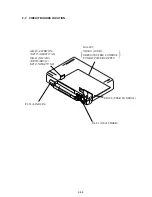
Page 27: ...RCUIT BOARDS LOCATION VIDEO AUDIO SERVO SYSTEM CONTROL TUNER POWER SUPPLY FJ 31 LINE 2 IN GK 12 ZWEITON EZ715AS EZ717AS NK 11 NICAM ED915 ED919 EZ715NZ EZ717NZ DI 81 DIAL TIMER DM 98 USER CONTROL MA 402 2 5E ...

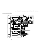
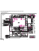
Page 28: ...5 ED616 ED815 ED817 ED818 ED915 ED919 EZ111 EZ212 EZ414 EZ715 EZ717 SEE PAGE 4 7 4 11 4 15 EXCEPT ED115 ED215 ED313 EZ111 EZ212 ED815 ED817 ED818 ED915 ED919 EZ715 EZ717 3 1 3 2 SECTION 3 BLOCK DIAGRAMS 3 1 OVERALL BLOCK DIAGRAM ...

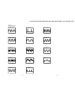
Page 29: ...MHz PAL IC201uaREC PB 608mVp p 3 58MHz NTSC REC 512mVp p H PB 584mVp p H IC201tk REC PB 320mVp p H IC201y REC PB IC2914 PB 2 2Vp p H IC291w PB 152mVp p H IC2914 REC 2 1Vp p H 2 36Vp p 15 7KHz IC101ql REC PB 2 16Vp p 15 7KHz IC101qj REC PB IC201t REC PB 4 6Vp p H IC201e REC PB 1 1Vp p H IC201whREC PB REC 512mVp p H PB 584mVp p H IC201wd REC PB REC 472mVp p H PB 504mVp p H IC201wa REC PB 392mVp p H ...

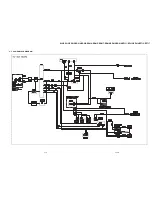
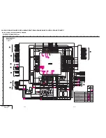
Page 30: ...5KHz IC1016REC PB 4 32Vp p 15 7KHz IC1016REC PB 3 8Vp p IC1019REC PB 2 6Vp p 31 847KHz IC101_REC PB 2 6Vp p 31 847KHz IC101 REC PB 5 0Vp p 25KHz IC1014REC 5 0Vp p 25KHz IC1013REC PB 5 0Vp p 25KHz IC1015REC PB 4 64Vp p 25KHz IC1013REC 4 64Vp p 25KHz IC1014REC 3 5 3 6 3 3 SERVO SYSTEM CONTROL BLOCK DIAGRAM ...

Page 31: ...SLV ED115 ED215 ED313 ED515 ED616 ED815 ED817 ED818 ED915 ED919 EZ111 EZ212 EZ414 EZ715 EZ717 3 4 AUDIO BLOCK DIAGRAM 3 7 3 8 ...

Page 32: ...SLV ED115 ED215 ED313 ED515 ED616 ED815 ED817 ED818 ED915 ED919 EZ111 EZ212 EZ414 EZ715 EZ717 3 5 TUNER BLOCK DIAGRAM 3 9 3 10 ...

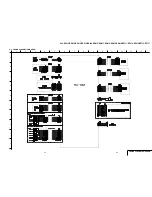
Page 33: ...SLV ED115 ED215 ED313 ED515 ED616 ED815 ED817 ED818 ED915 ED919 EZ111 EZ212 EZ414 EZ715 EZ717 3 6 MODE CONTROL BLOCK DIAGRAM 3 11 3 12 ...

Page 34: ...SLV ED115 ED215 ED313 ED515 ED616 ED815 ED817 ED818 ED915 ED919 EZ111 EZ212 EZ414 EZ715 EZ717 3 7 POWER BLOCK DIAGRAM 3 13 3 14E ...

Page 35: ...sed In such cases the unused circuits may be indicated Parts with differ according to the model destination Refer to the mount table for each function All variable and adjustable resistors have characteristic curve B unless otherwise noted Signal name XEDIT EDIT PB XREC PB REC non flammable resistor fusible resistor panel designation internal component B B Line B B Line Circled numbers refer to wa...

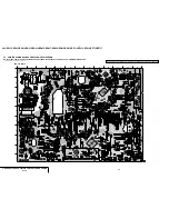
Page 36: ...1 2 3 4 5 6 7 8 9 10 11 12 13 14 B C D E F G H I J SLV ED115 ED215 ED313 ED515 ED616 ED815 ED817 ED818 ED915 ED919 EZ111 EZ212 EZ414 EZ715 EZ717 4 3 4 4 4 1 FRAME SCHEMATIC DIAGRAM FRAME SCHEMATIC DIAGRAM ...

Page 37: ... 9 10 11 12 13 B C D E F G H I J 4 6 MA 402 VIDEO AUDIO I O SERVO SYSTEM CONTROL TUNER MODE CONTROL POWER SUPPLY PRINTED WIRING BOARD Ref No MA 402 Board 1 000 Series There are few cases that the part printed on this diagram isn t mounted in this model VIDEO AUDIO SERVO SYSTEM CONTROL TUNER POWER MA 402 4 2 PRINTED WIRING BOARDS AND SCHEMATIC DIAGRAMS MA 402 Board ...

Page 38: ...F 1 D614 I 2 D623 C 1 D624 C 2 D625 D 1 D626 E 3 D701 C 12 D901 A 4 D902 A 6 IC031 I 4 IC101 H 8 IC141 I 5 IC142 I 12 IC201 C 10 IC291 D 6 IC301 A 10 IC451 I 7 IC502 J 5 IC600 D 2 IC601 G 1 IC660 H 1 IC662 C 12 IC701 H 13 Q001 F 3 Q002 F 11 Q003 F 7 Q151 H 7 Q152 H 7 Q153 I 10 Q171 H 5 Q172 G 5 Q173 G 5 Q174 G 5 Q175 G 6 Q191 G 8 Q192 G 8 Q201 C 10 Q202 D 11 Q203 D 7 Q204 D 7 Q206 B 9 Q210 E 10 Q2...

Page 39: ... JS202 16V 47u C378 XX L371 JS203 JL235 15 R380 10uH L206 JL223 100 R214 4700p C254 JL209 1u B C216 2200 R385 XX C212 JL205 2 2M R219 4700 R218 JL331 10uH L202 JL291 RFSWP JL202 UN2213 TX Q202 XX L351 0 001u C219 GND JL237 JL217 HC36 XX C213 RECP 4700p C257 1u B C224 1k R224 JL292 2200p C204 0 01u B C383 XX C264 CN204 XX 1 LP CH2 2 LP COM 3 LP CH1 4 SP CH2 5 SP COM 6 SP CH1 IC201 HA118217F 1 2 3 4...

Page 40: ...Vp p 4 43 MHz PAL 6 IC201 ua REC PB 608 mVp p 3 58 MHz NTSC 7 IC201 y REC PB 320 mVp p H 8 IC201 tk REC PB REC 512 mVp p H PB 584 mVp p H 9 IC201 t REC PB 4 6 Vp p H q IC201 e REC PB 1 1 Vp p H qa IC201 wh REC PB REC 512 mVp p H PB 584 mVp p H qs IC201 qk ql wd REC PB REC 472 mVp p H PB 504 mVp p H qd IC201 wa REC PB 392 mVp p H qf IC291 w PB 152 mVp p H qg IC291 4 qk REC 2 1 Vp p H qh IC291 qk PB...

Page 41: ...3 24 25 26 27 28 29 30 31 32 33 34 35 36 37 38 39 40 41 42 43 44 45 46 47 48 49 50 51 52 53 54 55 56 57 58 59 60 61 62 63 64 65 66 67 68 69 70 71 72 73 74 75 76 77 78 79 80 81 82 83 84 85 86 87 88 89 90 91 92 93 94 95 96 97 98 99 100 101 102 103 104 105 106 107 108 109 110 111 112 M103 T83 HT62 HT61 FL65 FL63 FL58 V59 V102 V100 FL64 M38 M39 S43 M9 M104 V18A A96 V109 V111 A89 V105 V60 V59 A72 A71 V...

Page 42: ...5 0 Vp p 25Hz 2 IC101 5 REC PB 5 0 Vp p 25Hz 3 IC101 3 REC 4 64 Vp p 25Hz 4 IC101 4 REC 4 64 Vp p 25Hz 5 IC101 4 REC 5 0 Vp p 25Hz 6 IC101 3 REC PB 5 0 Vp p 25Hz 7 IC101 9 REC PB 3 8 Vp p 8 IC101 REC PB 2 36 Vp p 15 7 KHz 9 IC101 REC PB 2 16 Vp p 15 7 KHz 0 IC101 REC PB 4 32 Vp p 15 7 KHz IC101 _ REC PB 2 6 Vp p 31 847KHz IC101 REC PB 4 3 Vp p 10 MHz JL 192 PB 4 64 Vp p 25 Hz IC101 E REC PB 5 0 Vp...

Page 43: ...R JL003 7P CN071 1 D VS 2 MTR GND 3 D FG 4 MTR 12V 5 D PG 6 GND 7 UN5V M CAM JL031 0 001u B C001 REC_PROOF 0 01u B C032 JL073 DRUM_PG JL002 CAP_FG 470 R001 16V 1000u C076 MPG06D 6052PKG3 D071 2 2uH L072 0 047u B C071 MODE4 JL072 47k R032 1k R076 25V XX C457 CAP_RVS M108 M91 MTR_GND MTR_12V M92 M86 M42 M38 M32 M104 M103 M38 M107 M33 M39 M32 GND GND_3 M85 M40 M107 M41 M49 M90 M108 M37 M45 M9 M39 M9 ...

Page 44: ...I_GND SW12V SW5V 0 1u F C323 UN5V HC35 HC37 JL361 JL360 JL362 JL363 JL364 JL365 JL366 JL367 JL369 JL370 JL372 JL373 JL374 JL375 AFENV HC36 JL376 JL377 HA21 HA22 XX L301 0 60mm JS361 XX L302 0 60mm JS362 JL378 0 R322 0 22u B C328 HT1 JL379 JL382 JL383 CL301 JL384 AF_REC_P JL385 470 R328 HIFI_GND 16V XX C306 BIAS_GND XX JS301 470 R310 NA IN NA OUT AUDIO R OUT AUDIO L OUT L1 AUDIO R L1 AUDIO L L2 AUD...

Page 45: ...E 10 CLOCK 11 DATA 12 NC 13 B 5V 14 LCOK 15 TU 32V 16 SW1 I M 19 SW2 DK M 20 AU OUT 21 SIF OUT 22 AFT 23 VIDEO OUT 24 HA22 470 R702 MOD_V JL738 0 JS703 0 60mm JS709 0 60mm JS711 XX JS713 AUDIO_OUT HT2 HT3 HT1 0 JS712 HT13 XX JS701 0 JS722 0 JS720 0 R703 0 R708 470 R734 470 R733 XX L707 16V XX C733 XX C734 0 R738 XX Q709 XX Q710 XX R739 XX B C735 270 R740 XX Q708 XX R741 XX JS736 820 R742 GND SCK T...

Page 46: ...W12V LINE1 HIFI_GND XX JS907 NA8 GND 470 R906 10V 470u C903 RD6 2ES T1B2 D902 RD6 2ES T1B2 D901 JS908 XX JS909 7P CN334 1 POWER 2 D GND 3 L2 AU R 4 HIFI_GND 5 L2 AU L 6 AN GND 7 L2 VIDEO JS309 JS310 JL218 JL301 JL302 50V 1u C386 50V 1u C385 JS303 POWER D_GND L2_AU_R L2_VIDEO L2_AU_L L2_AU_L IO_GND IO_GND HIFI_GND GND P2 P4 IN IN OUT IN OUT LINE OUT AUDIO OUT L1 OUT P5 P6 AUDIO LOUT AUDIO ROUT L1 A...

Page 47: ...R421 JL412 JL411 4700 R457 GND 47k R418 3300 R424 ND451 2 F 4 G1 5 G2 6 G3 7 G4 8 G5 9 G6 10 NC 11 NC 12 P16 13 P15 14 P14 15 P13 16 P12 17 P11 18 P10 19 P9 20 P8 21 P7 22 P6 23 P5 24 P4 25 P3 26 P2 27 P1 29 F 30 F 1 F 5P CN412 1 D_GND 2 A D1 IN 3 A D2 OUT 4 A D2 IN 5 A D1 OUT 10V 100u C451 JL422 JL455 1k R454 JL454 JL453 180 R402 DGND JL457 68 R400 15k R427 W001 W002 FLD_CS SCK1 SO1 SI1 ETR1 ETR2...

Page 48: ...ND JL613 R641 10 1 4W 30V XX C617 47u 50V C624 DGND SW5V XX C632 1uH L604 C630 0 01u B R643 1W 2 2 1uH L603 470u 10V C629 0 01u B C631 0 5 2k R612 50V 1u C612 1 4W 47 R616 1 10W 2200 R615 PC123FY2 PH600 1500 R614 0 5 120 R613 1 4W IC601 AN1431T TA 1 2 3 ET601 47u 50V C636 1 4W 1k R617 0 12u C613 220 1 4W R618 PQ05RD11 IC662 1 6V IN 2 5V OUT 3 GND 4 P CONT 0 01u C673 16V 100u C674 0 01u C633 T600 3...

Page 49: ...7AS There are few cases that the part isn t mounted in this model is printed on this diagram Waveform 1 IC001 qg REC PB 148 mVp p 4 MHz 05 1 673 269 11 GK 12 BOARD SIDE A 11 05 1 673 269 11 GK 12 BOARD SIDE B 11 VIDEO AUDIO SERVO SYSTEM CONTROL TUNER POWER SUPPLY FJ 31 LINE 2 IN GK 12 ZWEITON EZ715AS EZ717AS NK 11 NICAM ED915 ED919 EZ715NZ EZ717NZ DI 81 DIAL TIMER DM 98 USER CONTROL MA 402 MA 402 ...

Page 50: ...No NK 11 board 3 000 series SLV ED915 ED919 EZ715NZ EZ717NZ There are few cases that the part isn t mounted in this model is printed on this diagram NK 11 BOARD SIDE A 1 669 815 12 12 05 NK 11 BOARD SIDE B 1 669 815 12 12 05 740 mVp p 24 576 MHz Note The components identified by mark or dotted line with mark are critical for safety Replace only with part number specified NICAM NK 11 4 31 4 32 MA 4...

Page 51: ...35 LINE 2 IN R L AUDIO VIDEO REC VIDEO SIGNAL Y CHROMA AUDIO SIGNAL SIGNAL PATH ED515 ED616 ED818 ED915 ED919 EZ715 EZ717 ED515 ED616 ED818 ED915 ED919 EZ715 EZ717 ED818 ED915 ED919 EZ715 EZ717 ED818 ED915 ED919 EZ715 EZ717 MA 402 6 8 CN334 SEE PAGE 4 23 EXCEPT ED515 ED616 FJ 31 LINE 2 IN DM 98 FUNCTION JL468 S462 JL465 S466 S468 JL466 2200 R470 S463 1500 R469 S467 1500 R468 2200 R467 1500 R465 S4...

Page 52: ...R PUSH TURN MA 402 7 8 CN411 SEE PAGE 4 25 DI 81 DIAL TIMER PRINTED WIRING BOARD AND SCHEMATIC DIAGRAM Ref No DI 81 Board 2 000 Series DI 81 BOARD VIDEO AUDIO SERVO SYSTEM CONTROL TUNER POWER SUPPLY FJ 31 LINE 2 IN GK 12 ZWEITON EZ715AS EZ717AS NK 11 NICAM ED915 ED919 EZ715NZ EZ717NZ DI 81 DIAL TIMER DM 98 USER CONTROL MA 402 A 1 2 3 4 5 6 7 B C D DIAL TIMER DI 81 4 35E There are few cases that th...

Page 53: ...ity Signal CAP QR DRUM PG DRUM FG CAP FG CAP PWM DRUM PWM Pin No MA 402 IC101 91 MA 402 IC101 104 MA 402 IC101 103 I O O I I I O O Hi Z 4 4 4 7 9 TAPE THREADING PB Hi Z 4 4 4 7 9 TAPE UNTHREAD ING Hi Z 1 6 5 8 9 Hi Z 1 6 H L 7 9 PB PAUSE 2 1 6 5 7 9 SLOW x 2 Hi Z 1 6 5 8 9 Hi Z 1 6 5 8 9 CUE Hi Z 1 6 5 8 9 REVIEW Hi Z 1 6 5 8 9 RECORD Hi Z 1 6 H L 7 9 REC PAUSE 5 2 SYSTEM CONTROL SERVO PERIPHERAL ...

Page 54: ...L H 2 H L H L 4 4 4 L 1 1 1 1 2 H L 3 4 L 6 6 H L L L H 2 H L H L 4 H L 4 4 7 H H L H 2 3 3 4 H 6 6 7 H H L H 2 3 3 4 L 6 6 7 H H L H 2 3 3 4 H 6 6 7 H H L H 2 H L H L 4 H 6 6 7 H H L H 2 3 3 4 H 6 6 7 H L L L 2 3 3 4 H 6 6 7 H L L L 2 3 3 4 H 6 6 7 L L H L 2 3 3 4 L 6 6 7 H L L L 2 3 3 4 H 6 6 7 H L L L 2 H L H L 4 H 6 6 5 3 SYSTEM CONTROL MECHANISM BLOCK INTERFACE MA 402 BOARD IC101 1 Uncertaint...

Page 55: ...D ING PB SLOW x 2 CUE REVIEW REC Hi Z 1 H L L I O O O O O Hi Z 1 H L L Hi Z 1 H L L 5 4 SYSTEM CONTROL AUDIO BLOCK INTERFACE MA 402 BOARD IC101 1 25Hz PAL 30Hz NTSC 50 duty pulse approx 5 msec delayed from RF SW P O O D STOP FF REW PB PAUSE REC PAUSE Hi Z 1 H L L H 1 H L L H 1 H L L H 1 H L L H 1 H L L H 1 H L L H 1 L H H H 1 H L L AF RF envelope signal input terminal for automatic tracking ...

Page 56: ...END LED POWER CONT WRITE CONT BLUE BACK AUDIO DUB ETR 1 ETR 2 VCC Pin No Pin Name I O Function 57 58 59 60 61 62 63 64 65 66 67 68 69 70 71 72 73 74 75 76 77 78 79 80 81 82 83 84 85 86 87 88 89 90 91 92 93 94 95 96 97 98 99 100 101 102 103 104 105 106 107 108 109 110 111 112 I O I O I O I O I O O I O O O O O O O I O I I I O I O O I O O O O O O O O O I I I I O O O O O I Ground FLD ground Clock sign...

Page 57: ... Digital ground demodulator circuitry 37 N C Not used 38 N C Not used 39 EXTI R I External audio input right channel 40 EXTI L I External audio input left channel 41 V REF2 I Analog reference voltage digital to analog converter and operational amplifiers 42 N C Not used 43 VDD A3 Analog power supply 5V operational amplifiers 44 VSS A3 Analog ground operational amplifiers 5 7 ZWEITON PROCESSOR PIN ...

Page 58: ...layed Table 6 1 Error Codes Table 6 2 Mode Codes in Case of Error Display tube lower 5 digits A B Code Description 0 NO ERROR 1 CAM ENCODER ERROR LOAD DIRECTION 2 CAM ENCODER ERROR UNLOAD DIRECTION 3 T REEL ERROR 4 S REEL ERROR 5 CAPSTAN ERROR 6 DRUM ERROR 7 INITIALIZE ERROR 8 CASSETTE UNLOADING ERROR 9 RESERVED Code Description 0 EJECT POWER ON 1 EJECT POWER OFF 2 UNLOAD STOP 3 STOP POWER ON 4 PO...

Page 59: ...e 7 6 Fig 7 2 2 2 1 4 Alingment Tapes Alignment Tape KRV 51N2 KRV 51P 2 1 3 Set up of Adjustment In this adjustment PAL or NTSC pattern generator is connected with LINE input signal terminal When checking with tuner connected AERIAL terminal Check that the amplitudes of video signal SYNC signal of picture portions and of burst signals are flat at approximately 0 3 0 7 and 0 3 V respectively and th...

Page 60: ...he RF switching position adjustment mode 2 Check appear A P on FL display 3 Using the channel and buttons adjust to 6 5 0 5 H 4 Press the pause button Fig 7 2 3 Mode E E Measuring Instrument Digital voltmeter F F check Measurement Point Between JL 615 IF and JL 614 F Specified Value 3 0 1 0 V 13 V check Measurement Point JL 625 Specified Value 11 0 1 5 V 6 V check Measurement Point JL 611 Specifie...

Page 61: ...mode 3 Check appear A H on FL display 4 Using the channels and buttons minimize a chipped portion At this time confirm that a noisy sound is not heard 5 Press the pause button Fig 7 2 5 2 Frequency Response Check Purpose Confirm that the frequency characteristic is within the specification Mode REC and PB SP LP mode Signal 400 Hz 17 5 dBs 20 Hz 17 5 dBs 20 kHz 17 5 dBs Measurement point Audio outp...

Page 62: ... Overall Level Characteristic and Distortion Factor Check 5 Overall S N Check 1 ACE Head Adjustment Refer to the SERVICE MANUAL of VHS MECHANICAL ADJUSTMENT VI 2 E E Output Level Check SLV ED115 ED215 ED313 ED515 ED616 EZ111 EZ212 EZ414 Purpose Confirm that the output level against the reference input is within the specification Mode E E Signal L R 400 Hz 7 5 dBs Measurement point Audio output ter...

Page 63: ... S N Check Purpose Confirm that the S N is within the specification Mode REC and PB SP mode Signal Short Measurement point Audio output terminal Measurement equipment Audio noise meter Specified value 46 0 dBs or less Confirmation Method 1 Connect both L and R channels of audio line input to the GND 2 Start recording 3 Play the recorded part to confirm that the noise is below 46 0 dBs 2 5 TUNER SY...

Page 64: ...2 6 PARTS ARRANGEMENT DIAGRAM FOR ADJUSTMENTS MA 402 BOARD Side A GK 12 BOARD Side A CN202 4 1 JS401 RV001 IC001 1 11 33 34 44 22 12 23 SEPARATION ADJ 7 6E ...

Page 65: ...A 6713 889 A FJ 031 COMPLETE PWB ED818 ED915 ED919 9 1 757 665 11 CORD POWER ED115 ED215 ED313 ED515 ED616 ED815 ED817 ED818 ED915 ED919 9 1 777 855 51 CORD POWER EZ111 EZ212 EZ414 EZ715 EZ717 10 3 064 641 41 CASE UPPER ED215 ED515 ED616 ME SG ED815 ED817 ED818 ME SG ED915 ED919 EZ715 EZ717 10 3 064 641 71 CASE UPPER ED115 ED313 ME SG The components identified by mark or dotted line with mark are ...

Page 66: ... 21 SUMITITE B3 BV 54 1 757 690 11 CABLE FLAT FMD 022 ED515 ED616 ED815 ED817 ED818 ED915 ED919 EZ414 EZ715 EZ717 54 1 757 691 11 CABLE FLAT FMD 023 ED115 ED215 ED313 EZ111 EZ212 55 A 6713 875 A NK 11 BOARD COMPLETE ED915 ED919 ED715NZ EZ717NZ 55 A 6713 872 Z GK 12 BOARD COMPLETE EZ715AS EZ717AS 56 1 757 551 11 CABLE FLAT FAC 009 57 X 3951 402 1 PANEL ASSY REAR ED919 ED915 ED815 ED817 ED818 EZ715 ...

Page 67: ... ASSY SL 708 3 977 535 01 PLATE LUMINOUS END SENSOR 709 3 977 536 01 PLATE LUMINOUS TOP SENSOR 710 3 977 443 01 WASHER STOPPER 711 A 6759 863 B PRESS BLOCK ASSY PINCH 712 3 958 455 01 SPRING PINCH TENSION 713 3 977 447 01 GEAR ELEVATOR 714 3 063 773 02 OPENER LID SL 715 3 977 441 03 GEAR PINCH PRESSING 716 3 977 445 02 GEAR TG8 ARM DRIVING 717 3 062 763 01 SPRING EXTENSION RVS BRAKE 718 X 3950 964...

Page 68: ...758 X 3950 966 1 TG1 ASSY SL 759 3 063 958 01 SPRING COMP SL PEND 760 3 977 488 01 SPRING EXTENSION POWER TENSION 761 A 6775 922 A SHUTTLE S BLOCK ASSY 762 X 3949 910 2 G ROLLER ASSY 763 3 965 178 01 SPRING 764 3 062 687 01 BASE DRUM K UPPER MOTOR 765 A 6750 328 E SHUTTLE T BLOCK ASSY 766 3 977 501 01 PLATE LUMINOUS 767 A 6746 074 G ROLLER BLOCK ASSY HC 768 X 3947 255 1 ROLLER ASSY HC 769 3 975 72...

Page 69: ...1 3 977 516 01 HOLDER FL SLIDER 812 3 977 877 01 PLATE RETAINER 813 3 977 504 01 GEAR CLUTCH 814 X 3947 365 1 GEAR ASSY PULLEY B 815 3 977 510 01 BELT RUBBER 816 3 056 824 01 WASHER STOPPER 817 3 063 439 01 GEAR CAM 818 3 063 768 01 SLIDER SL 819 3 063 757 01 GEAR LOADING T H R 820 3 977 456 03 SPRING TORSION LOAD T 821 X 3948 132 2 LEVER ASSY LOADING T 822 3 063 783 01 GEAR LOADING S H R 823 3 97...

Page 70: ...ONNECTOR FFC FPC 7P CN532 1 784 449 11 CONNECTOR FFC FPC 7P JACK CNJ531 1 770 021 11 JACK PIN 3P ED515 ED616 ED818 ED915 ED919 EZ715 EZ717 DIODE D531 8 719 071 15 DIODE HZM6 8ZWA1TL ED515 ED616 ED818 ED915 ED919 EZ715 EZ717 D532 8 719 071 15 DIODE HZM6 8ZWA1TL ED515 ED616 ED818 ED915 ED919 EZ715 EZ717 D533 8 719 071 15 DIODE HZM6 8ZWA1TL ED515 ED616 ED818 ED915 ED919 EZ715 EZ717 D534 8 719 017 09 ...

Page 71: ...1 10W R009 1 216 041 00 METAL CHIP 470 5 1 10W R010 1 208 803 11 METAL CHIP 7 5K 0 5 1 10W R011 1 216 295 00 METAL CHIP 0 5 1 10W R012 1 216 298 00 METAL CHIP 2 2 5 1 10W VARIABLE RESISTOR RV001 1 241 783 11 RES ADJ CARBON 2 2K VIBRATOR X001 1 781 353 11 VIBRATOR CRYSTAL 4MHz A 6713 865 A MA 402 BOARD COMPLETE ED818 A 6713 866 A MA 402 BOARD COMPLETE ED919 A 6713 867 A MA 402 BOARD COMPLETE EZ717N...

Page 72: ...164 489 11 CERAMIC CHIP 0 22uF 10 00 16V C168 1 164 004 11 CERAMIC CHIP 0 1uF 10 00 25V C169 1 163 038 00 CERAMIC CHIP 0 1uF 25V C171 1 163 038 00 CERAMIC CHIP 0 1uF 25V C172 1 163 245 11 CERAMIC CHIP 56PF 5 00 50V C191 1 163 137 00 CERAMIC CHIP 680PF 5 00 50V ED616 ED818 EZ717 C192 1 163 145 00 CERAMIC CHIP 0 0015uF 5 00 50V C193 1 164 004 11 CERAMIC CHIP 0 1uF 10 00 25V C194 1 124 589 11 ELECT 4...

Page 73: ...3 11 ELECT 4 7uF 20 00 50V ED616 ED817 ED818 ED915 ED919 EZ717 C299 1 164 232 11 CERAMIC CHIP 0 01uF 10 00 50V ED616 ED817 ED818 ED915 ED919 EZ717 C303 1 164 505 11 CERAMIC CHIP 2 2uF 16V C304 1 164 232 11 CERAMIC CHIP 0 01uF 10 00 50V C307 1 124 589 11 ELECT 47uF 20 00 16V C308 1 126 964 11 ELECT 10uF 20 00 50V C309 1 163 020 00 CERAMIC CHIP 0 0082uF 10 00 50V C310 1 104 664 11 ELECT 47uF 20 00 2...

Page 74: ...CT 100uF 20 00 16V C713 1 164 232 11 CERAMIC CHIP 0 01uF 10 00 50V C714 1 164 232 11 CERAMIC CHIP 0 01uF 10 00 50V C715 1 163 037 11 CERAMIC CHIP 0 022uF 10 00 50V ED919 C719 1 163 038 00 CERAMIC CHIP 0 1uF 25V ED915 ED919 EZ715 EZ717 C722 1 126 933 11 ELECT 100uF 20 00 16V ED915 ED919 EZ715 EZ717 C723 1 164 232 11 CERAMIC CHIP 0 01uF 10 00 50V ED915 ED919 EZ715 EZ717 C730 1 163 009 11 CERAMIC CHI...

Page 75: ... IC AN1431T TA IC660 8 759 438 18 IC PQ12RD08 IC662 8 759 471 81 IC PQ05RD11 CHIP CONDUCTOR JR001 1 216 295 00 SHORT 0 JR002 1 216 295 00 SHORT 0 JR003 1 216 295 00 SHORT 0 JR004 1 216 295 00 SHORT 0 JR005 1 216 295 00 SHORT 0 JR006 1 216 295 00 SHORT 0 JR007 1 216 295 00 SHORT 0 JR008 1 216 295 00 SHORT 0 JR009 1 216 295 00 SHORT 0 JR010 1 216 295 00 SHORT 0 JR011 1 216 295 00 SHORT 0 JR012 1 216...

Page 76: ...EZ717 JS901 1 216 295 00 SHORT 0 JS902 1 216 295 00 SHORT 0 ED815 ED817 ED818 ED915 ED919 EZ715 EZ717 JS904 1 216 295 00 SHORT 0 ED515 ED616 EZ414 JS905 1 216 296 00 SHORT 0 JS906 1 216 295 00 SHORT 0 ED115 ED215 ED313 ED515 ED616 EZ111 EZ212 EZ414 COIL L006 1 412 945 11 INDUCTOR 3 3uH L071 1 414 185 51 INDUCTOR 22uH ED313 EZ111 EZ212 L072 1 414 179 51 INDUCTOR 2 2uH L151 1 414 185 51 INDUCTOR 22u...

Page 77: ...016 1 216 033 00 RES CHIP 220 5 1 10W R032 1 216 089 00 RES CHIP 47K 5 1 10W R034 1 216 689 11 RES CHIP 39K 5 1 10W R035 1 216 689 11 RES CHIP 39K 5 1 10W R051 1 249 425 11 CARBON 4 7K 5 1 4W R052 1 216 065 00 RES CHIP 4 7K 5 1 10W R053 1 247 843 11 CARBON 3 3K 5 1 4W R056 1 249 425 11 CARBON 4 7K 5 1 4W R057 1 216 073 00 RES CHIP 10K 5 1 10W R071 1 216 103 00 RES CHIP 180K 5 1 10W R072 1 216 089 ...

Page 78: ...1 10W R224 1 216 049 00 RES CHIP 1K 5 1 10W R225 1 249 417 11 CARBON 1K 5 1 4W R226 1 216 099 00 RES CHIP 120K 5 1 10W R227 1 216 049 00 RES CHIP 1K 5 1 10W R228 1 216 049 00 RES CHIP 1K 5 1 10W R289 1 216 049 00 RES CHIP 1K 5 1 10W ED616 ED817 ED818 ED915 ED919 R291 1 208 806 11 METAL CHIP 10K 0 5 1 10W ED616 ED817 ED818 ED915 ED919 R294 1 247 807 31 CARBON 100 5 1 4W ED616 ED817 ED818 ED915 ED91...

Page 79: ...6 11 CARBON 120 5 1 4W R614 1 216 655 11 METAL CHIP 1 5K 0 5 1 10W R615 1 216 057 00 RES CHIP 2 2K 5 1 10W R616 1 249 401 11 CARBON 47 5 1 4W R617 1 249 417 11 CARBON 1K 5 1 4W R618 1 249 409 11 CARBON 220 5 1 4W R640 1 219 153 11 FUSIBLE 10 5 1 4W R641 1 219 153 11 FUSIBLE 10 5 1 4W R643 1 216 353 00 METAL OXIDE 2 2 5 1W R647 1 215 465 00 METAL 68K 1 1 4W R648 1 216 057 00 RES CHIP 2 2K 5 1 10W R...

Page 80: ...1 163 989 11 CERAMIC CHIP 0 033uF 10 25V C019 1 109 982 11 CERAMIC CHIP 1uF 10 00 10V C020 1 164 004 11 CERAMIC CHIP 0 1uF 10 25V C021 1 113 642 11 TANTALUM CHIP 47uF 10 00 10V C022 1 107 823 11 CERAMIC CHIP 0 47uF 10 00 16V C023 1 163 243 11 CERAMIC CHIP 47PF 5 00 50V CONNECTOR CN001 1 691 183 11 CONNECTOR BOARD TO BOARD 13P DIODE D001 8 719 066 72 DIODE BB135 FERRITE BEAD FB001 1 543 813 21 FERR...

Page 81: ... 476 475 11 COMMANDER STANDARD RMT V311 ED115 ED215 ED313 ED515 ED815 1 476 475 21 COMMANDER STANDARD RMT V311A ED817 ED915 1 476 475 21 COMMANDER STANDARD RMT V311E EZ111 1 476 475 41 COMMANDER STANDARD RMT V311C ED919 1 476 475 31 COMMANDER STANDARD RMT V311B ED616 ED818 1 476 475 61 COMMANDER STANDARD RMT V311E EZ715 1 476 475 51 COMMANDER STANDARD RMT V311D EZ212 EZ414 1 476 473 11 COMMANDER S...

Page 82: ...f No Part No Description Remarks 8 20 107 Sony Corporation NETWORK ENTERTAINMENT GROUP 2001A0800 1 2001 1 Published by Quality Assurance Dept 9 921 787 11 SLV ED115 ED215 ED313 ED515 ED616 ED815 ED817 ED818 ED915 ED919 EZ111 EZ212 EZ414 EZ715 EZ717 ...

Reviews: