background image

11

qf

Parallel port (D-sub, 25-pin)
This port is used to connect to a custom-made
external control unit to control the device. Refer to
the pin assignments in the “Specifications and
Troubleshooting” chapter of this guide.

qg

PS2 port (2, mini DIN, 6-pin)
These ports are used for servicing purposes only.

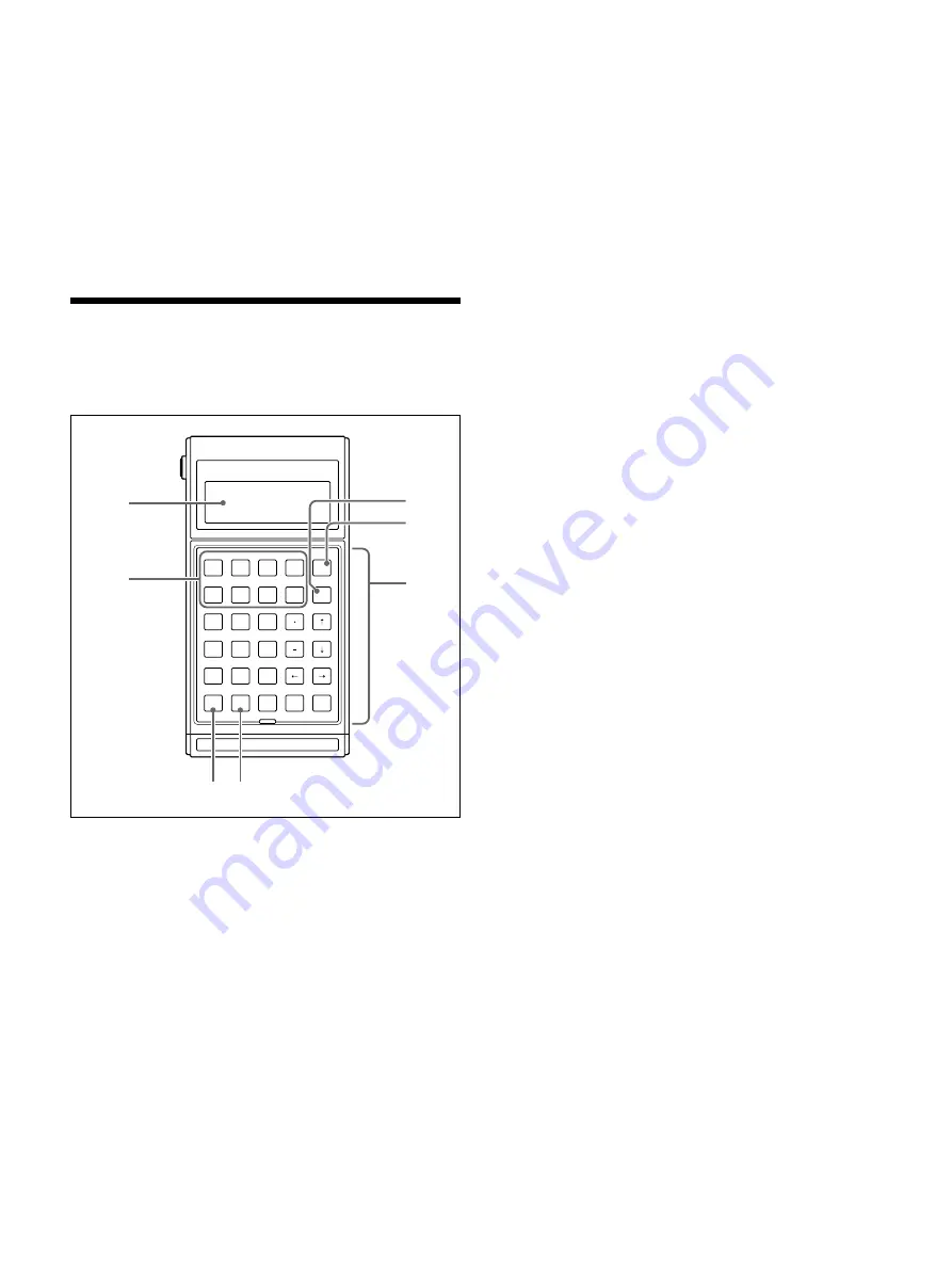
Remote Control

This section describes the RM-P110 Remote Control
Unit (sold separately).

D

B

A

C

I

H

F

E

G

N

M

K

J

L

S

R

P

O

Q

X

W

U

T

V

Z

Y

ESC

F4

F2

F1

F3

BS

F8

F6

F5

F7

2

1

3

5

4

6

8

7

9

ENT

SP

ABC

abc

RM-P110

0

1

Display
The LCD display of the remote control displays
messages and input commands. It can display 4
lines of 20 alphanumerical characters.

2

Keyboard
The keyboard is composed of 26 alphanumerical
keys, 8 function keys, a backspace key, an escape
key, a space key, and an enter key.

3

Escape key
The [ESC] key allows you to cancel an operation,
such as typing the name of a doctor.

4

Backspace key
The [BS] key allows you to go back one space to
correct mistakes.

5

[ABC] key
Allows you to enter uppercase text. The operation
of this key can be changed. Refer to the RM-P110
Remote Control Unit User’s Guide for details.

6

[abc] key
Allows you to enter lowercase text. The operation
of this key can be changed. Refer to the RM-P110
Remote Control Unit User’s Guide for details.

7

Function keys
You can assign strings of up to 16 characters to
each of the 8 function keys. This allows you to
assign doctor names, patient names, or procedure
names to the function keys. Refer to the RM-P110
Remote Control Unit User’s Guide for details.

1

2

4

3

5

6

7

Summary of Contents for RM-P110

Page 1: ...Digital Capture Unit Remote Control Unit 3 206 230 11 1 UPA P100MD RM P110 User s Guides 2001 Sony Corporation ...

Page 2: ...customers in Canada for UPA P100MD This unit has been certified according to Standard CSA C22 2 NO 601 1 For UPA P100MD Important safeguards notices for use in the medical environments 1 All the equipments connected to this unit shall be certified according to Standard IEC60601 1 IEC60950 IEC60065 or other IEC ISO Standards applicable to the equipments 2 When this unit is used together with other ...

Page 3: ...20 to 80 no condensation allowed Protection against electric shock Class I Protection against harmful ingress of water Ordinary Degree of safety in the presence of flammable anesthetics or oxygen Not suitable for use in the presence of flammable anesthetics or oxygen Mode of operation Continuous Design and specifications are subject to change without notice ...

Page 4: ...next to the D sub connectors on the rear panel of the unit are threaded in inches When using cables other that the one provided for use with this unit make sure that you use inch threaded screws Do not connect the RM P110 to the UPA P100MD when it is on Please make sure that the UPA P100MD is off before connecting the RM P110 Connecting the RM P110 to the UPA P100MD when it is on could cause it to...

Page 5: ...Digital Capture Unit UPA P100MD User s Guide ...

Page 6: ...e Using the Digital Capture Unit 4 About the Hard Disk 4 About the rear connectors 4 About the CD R 4 Overview Digital Capture Unit Overview 7 Features 8 Built in CD R 8 Remote Control Unit 8 Linux Operating System 8 Networking Capabilities 8 Direct Printout Capabilities 8 Presentation of the Digital Capture Unit Front Panel 9 Rear Panel 10 Remote Control 11 Setup Preliminary Connections 12 Prelim...

Page 7: ...P O Q X W U T V Z Y ESC F4 F2 F1 F3 BS F8 F6 F5 F7 2 1 3 5 4 6 8 7 9 ENT SP ABC abc RM P110 0 RM P110 Remote Control Unit UP D50 or UP D70XR Digital Color Printers AC Power Inlet External Control Device not provided by Sony PC Network if applicable Video Device The illustration above presents the connections of the UPA P100MD For explanations about the UPA P100MD connectors and rear panel see Rear...

Page 8: ... not require long shutdown and start up procedures This means that you can turn the unit on or off as you like except when writing information on a CD R disc or the hard disk Networking Capabilities Although the Digital Capture Unit is connected to a single computer during setup it can also be configured for use through a local area network LAN This is highly useful when it is necessary for severa...

Page 9: ...an be accessed from any CD ROM drive 3 CD R drive eject button This button is used to open or close the CD R drive When writing to a CD R disc this button should not be used Note Because the CD R tray opens automatically after writing on a disc do not place any obstruction in front of the CD R tray 4 CD R drive Busy indicator This indicator blinks when the CD R drive is busy writing information on...

Page 10: ... Video input RCA PIN jack Input analog video signals Connect to the optical device s video output 5 S video input mini DIN 4 pin Input analog s video signals Connect to the optical device s s video output 6 SCSI port half pitch 50 pin This port connects to a digital color printer Compatible printers are the UP D50 and UP D70XR Their SCSI default settings are Terminator on ID 001 Refer to the appro...

Page 11: ...eyboard is composed of 26 alphanumerical keys 8 function keys a backspace key an escape key a space key and an enter key 3 Escape key The ESC key allows you to cancel an operation such as typing the name of a doctor 4 Backspace key The BS key allows you to go back one space to correct mistakes 5 ABC key Allows you to enter uppercase text The operation of this key can be changed Refer to the RM P11...

Page 12: ...rallel port on the rear panel of the UPA P100MD 5 On the rear panel of the UPA P100MD locate the network port Connect a LAN cross cable to this port 6 Connect the other end of the LAN cross cable to the network port of your computer You are now ready to make preliminary settings Note Before connecting the unit make sure that you are using the appropriate type of cross cable If you are not sure of ...

Page 13: ...e click Network The Network dialog box appears 4 On the Configuration tab click TCP IP Note If there is more than one TCP IP entry in the Network dialog box make sure that you select the TCP IP that belongs to the network adapter 5 With TCP IP selected click Properties The TCP IP Properties dialog box appears 6 Click the IP Address tab 7 On the IP Address tab click Specify an IP address 8 In the I...

Page 14: ... by the UPA P100MD The procedures in this guide are based on Windows 98 dialog boxes and windows Screen appearance may differ slightly in other Windows versions 1 Using an RJ 45 cross cable 10Base T or 100Base TX connect the UPA P100MD directly to the appropriate network interface on your computer 2 Turn on the unit and wait until it is ready for operations 3 On your computer start your Internet b...

Page 15: ...wser 11 Disconnect the unit from your computer and connect it to the network If you are unsure of how to connect the unit to your network ask your system administrator Configuring the UPA P100MD Before using the UPA P100MD you need to configure it through the configuration screen Follow the procedure below to configure the UPA P100MD 1 Turn on a computer connected to the network to which the UPA P...

Page 16: ...characters upper and lowercase and hyphens with the UPA P100MD All other characters are rejected including spaces In the configuration screen an error message appears to tell you so when you click Save Config to inform you if there are illegal characters in use or a name exceeds the maximum permitted length This setting needs to be adjusted according to the type of incoming video signal PAL or NTS...

Page 17: ...deleted The maximum number of days you can set is 60 For examples if you type 10 days in this box all the files and folders on the Digital Capture Unit hard disk are deleted after 10 days Users that save large numbers of images every day should be careful of the number of days that they set here It should be set so that there are never more than 5000 images on the unit s hard disk at any one time ...

Page 18: ... list as the display language By default this language is English Also note that the configuration screen language is not affected by this setting Be sure to select this check box when you want to capture images from an analog printer synchronized with the UPA P100MD The capture of images is delayed by the time specified in the Delay value in milliseconds box By default this is 250 In this box ent...

Page 19: ...the screen above appears 2 Using the remote control keyboard enter the patient s name The patient s name has a maximum length of 18 alphanumerical characters Press ENT Enter Doctors name appears Enter Doctors name 3 Using the remote control keyboard enter the name of the doctor performing the procedure The doctor s name has a maximum length of 18 alphanumerical characters Press ENT Enter Procedure...

Page 20: ... see Saving Images to CD R discs or finish the operation by pressing 0 on the keyboard of the remote control Pressing 0 returns the display to Enter Patients Name so you can begin a new operation immediately To preview the images that you have captured and saved on the Digital Capture Unit hard disk refer to Viewing Images Viewing Images To be able to see the images that you have captured and save...

Page 21: ...e appears on the right as illustrated below Sample images Note When you click a thumbnail it opens as a JPEG file When you click the JPEG it opens as a TIFF files and can be saved To view other files click another thumbnail bb or BB Click Top to go back to the Choose a doctor screen Whenever you access a screen that contains image files click Refresh to update it and make sure you are looking at t...

Page 22: ...ssible to write images from the unit to a CD R disc ISO 9660 format Joliet Rock Ridge extension which can later be accessed from a different CD ROM drive or archived for reference Follow the procedure below to save data to a CD R disc using the Digital Capture Unit s CD R drive Note If you want to print images we recommend that you do so before saving images to a CD R disc because the UPA P100MD r...

Page 23: ...with the UPA P100MD proceed as explained below Note You must use a PC equipped with a MultiRead drive to be able to read this CD R disc A MultiRead MR drive is a drive with the ability to read all of the following types of media CD DA CD ROM CD R and CD RW 1 Insert the CD R disc into the CD ROM drive of your computer 2 On the desktop double click My Computer 3 In the My Computer window double clic...

Page 24: ...he first of the two messages above appears you should back up the oldest images on the UPA P100MD hard disk Follow one of the procedures below to clear space on the UPA P100MD hard disk for new images Saving Images to Your Computer 1 Follow the procedure outlined in Viewing Images to access the images of specific doctors and patients on the UPA P100MD 2 Click the thumbnail of the first image that ...

Page 25: ...When Enter Procedure name appears enter any procedure name then press the ENT key It does not matter what procedure name is entered 6 Insert a blank CD R disc in the UPA P100MD CD R drive 7 Without capturing any additional images press 3 on the remote control keyboard All the images for the doctor s and patient s entered in steps 3 and 4 are written to the CD R disc 8 Repeat for other patients and...

Page 26: ...ron 566 MHz or faster 64 MB or more 20 GB or more Linux CD R discs TIFF JPEG NTSC 640 480 pixels PAL 758 576 pixels PAL 712 480 CCIR601 Write 12 Read 32 1 0 V p p 75 Ω Y 1 0 V p p 75 Ω C 1 0 V p p 75 Ω SCSI 2 For service use only RM P110 Remote Control Unit only Not supported Not supported For service use only Not supported Not supported Not supported Not supported 100 240 V 50 60 Hz 60 W 0 6 A 0 ...

Page 27: ...to the UPA P100MD and when each full page of images is captured Start of printing or saving images to a CD R disc When using the RM P110 Remote Control Unit this signal is output when you push 2 or 3 Problem when writing images to a CD R disc Printer initialization error Print or Burn is selected Audible signal Low pitch beep 200 Hz 0 5 s 3 consecutive high pitch beeps 1000 Hz 0 25 s each High pit...

Page 28: ...me 2 DATA0 Not supported by the unit at this time 3 DATA1 Not supported by the unit at this time 4 DATA2 Not supported by the unit at this time 5 DATA3 Not supported by the unit at this time 6 DATA4 Not supported by the unit at this time 7 DATA5 Not supported by the unit at this time 8 DATA6 Not supported by the unit at this time 9 DATA7 Not supported by the unit at this time 10 ACK BURN 11 BUSY E...

Page 29: ... 6 DSR 7 RTS 8 CTS 9 RI Not supported by the unit at this time Warning This connector outputs 5 V therefore do not connect it to any device other than the RM P110 Remote Control Unit or other control device designed for use with the UPA P100MD If you connect a device other than the remote control to this connector there is a risk of damage to the device Note The screws of the remote control port o...

Page 30: ...e the UPA P100MD Verify that there is a CD R disc in the CD R drive Verify that your are using a blank CD R disc If you use a previously written CD R disc check that it was written in the UPA P100MD Multi session recording mode CD R discs written in the Single session recording mode or on other systems cannot be used Verify that the CD R disc in the tray is of a supported type Refer to General Spe...

Page 31: ...Remote Control Unit RM P110 User s Guide ...

Page 32: ...Size 33 Large Display 33 8 Function Keys 33 RS 232C Port 33 Setup Connecting the Remote Control Unit 34 Operation Remote Control Setup Mode 35 Programming Function Keys 37 Specifications 38 Display 38 Controller 38 Keyboard 38 Default Operating States 38 Remote Control Messages 38 ...

Page 33: ...nd light making it very easy to use Large Display The remote control unit is equipped with an LCD that can display 4 rows of 20 characters each for easy readability 8 Function Keys The remote control comes with 8 function keys that can be used to save strings of up to 16 characters to each of the 8 function keys This allows you to assign doctor names patient names or procedure names to the functio...

Page 34: ...nit follow the procedure below 1 On the rear panel of the Digital Capture Unit locate the remote control port 2 Connect the remote control connector to the remote control port 3 Secure the connector by tightening the screws Warning Do not overtighten the screws as this could damage the connector or the remote control port ...

Page 35: ...P MODE End Communication Display Keyboard RS 232C signals 2 Using the T or t keys move the cursor to the setting that you want to modify Press the ENT key to select a mode Refer to the table on the next page for the meaning of the display items in this screen 3 Use the T and t keys to move to the desired item Use the R and r keys to change the setting Repeat for other settings When you finish maki...

Page 36: ...SC key sends the hexadecimal character codes 1B and 0D to the UPA P100MD The ESC key has the same effect as the ENT key Select the position to which the cursor moves when a horizontal tab is received Available choices are 1 5 and 10 By default this is 1 Select how the cursor moves when a carriage return is received Available choices are Cr carriage return only and Cr Lf carriage return and line fe...

Page 37: ...name 3 Press the ENT key to select the function key Three lines of the 165 programmable characters appear at the top of the 4 line display 0123 456789 ABCDEFG HIJKLMNOPQRSTUVWXYZ F1 4 Use the arrow keys to move the cursor to the first character that you want to use Press ENT The blinking character appears at the end of the string at the bottom of the display Repeat this step as necessary Note The ...

Page 38: ... occurred when writing images to a CD R disc Enter Doctors name This message appears when you need to enter the doctor s name directly or by pressing a function key on the remote control unit Specifications This section contains the hardware specifications of the device Display Controller Keyboard Display Type Display Field Display Area Character Size Displayable Character Type Cursor STN type LCD...

Page 39: ... not configured This message appears when the Video Printer Support check box in the configuration screen is not selected and you push the 2 key print command on the remote control keyboard Rebooting system This message appears when you click the Save config button indicating that the unit is restarting Booting system This message appears while the UPA P100MD is starting when you turn it on Hard D...

Reviews: