background image

6

RM-AX4000

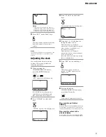
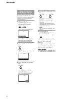
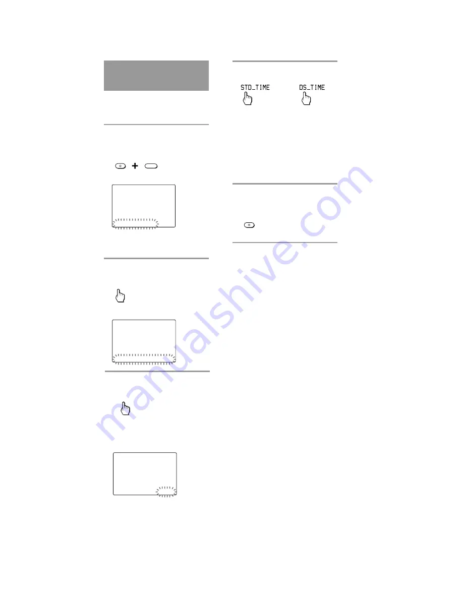
To change the display to
the daylight savings time
(summer time) indication

You can select the standard time
(STD_TIME) or summer time (DS_TIME).
To change this setting, perform the
following procedure.

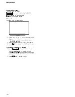
1

While pressing the
COMMANDER OFF button,
press the MUTING button.

MUTING

OFF

COMMANDER

 “SET” appears as the Display title.

SET

SU

LEARN
NG

 LIGHT  DISPLAY  OTHER

If “OTHER” does not flash on the
Label keys, press the Display title
(SET) repeatedly until it appears.

2

Press “OTHER” on the Label
keys.

OTHER

“OTHER” appears as the Display title.

OTHER

SU

LEARN
NG

  BEEP  DS_TIME  CLOCK   RESET

3

Press “DS_TIME” on the Label
keys.

DS_TIME

The setting display for daylight
savings time appears.
The current setting is shown inside
the [ ], while the other flashes.

OTHER

SU

LEARN
NG

DS_TIME [STD_TIME]      DS_TIME

4

Press the STD_TIME or DS_TIME
key.

STD_TIME is 1 hour behind the
DS_TIME.
DS_TIME is 1 hour ahead of the
STD_TIME.
The setting of the daylight savings
time changes and a beep sounds each
time you press the keys.

Note

In this case, the minute and second are not
changed.

5

Press and hold the
COMMANDER OFF button for
more than 2 seconds.

OFF

COMMANDER

The Remote Commander turns off.

or

If you want to quit before
finishing

Press and hold the COMMANDER OFF button
for more than 2 seconds. The previous status
returns, and the Remote Commander turns off.

If you want to return to the
previous display

Press the BACK button or the COMMANDER
OFF button, the previous LCD display returns.

Summary of Contents for RM-AX4000 - Integrated Remote Commander

Page 1: ...V turned on off up to approx 300 times per day Dimensions Approx 4 3 4 1 1 4 7 in w h d 118 31 2 175 mm Mass 12 oz 320 g not including batteries Learnable signals Capacity per signal up to 300 bit Signal frequency range 455 kHz and up to 300 kHz Signal interval up to 1 second Some signals cannot be learned by the Remote Commander even though the signals comply with these specifications Design and ...

Page 2: ...ng use of unleaded solder are printed with the lead free mark LF indicating the solder contains no lead Caution Some printed circuit boards may not come printed with the lead free mark due to their particular size LEAD FREE MARK Unleaded solder has the following characteristics Unleaded solder melts at a temperature about 40 C higher than ordinary solder Ordinary soldering irons can be used but th...

Page 3: ...tton qs Display title Shows the title of the LCD Display If a page number such as 1 appears multiple pages are available If you press the number next page displays qd Touch keys The keys are used for setting the Remote Commander and operating each component appear on the LCD display Note Do not press the touch keys using sharp objects such as pins or ball point pens qf SYNC UP button pages 25 49 5...

Page 4: ...ep sounds SET and SU flash and 12 00 AM lights on the Clock display CLOCK SU AM LEARN NG SET STD_TIME 3 Set the day of the week by pressing the F or f button The selected day of the week flashes Next press the g button The day of the week is set 12 hour AM and SET flash CLOCK SU AM LEARN NG SET STD_TIME Note If you press the G button the day of the week is set and setting mode skips to step 5 or S...

Page 5: ...ARN NG BEEP DS_TIME CLOCK RESET SET SU LEARN NG PRESET LEARN MACRO TIMER 3 Press CLOCK on the Label keys CLOCK The setting display for clock appears CLOCK SU AM LEARN NG SET STD_TIME 4 Press the F f g G buttons to change the time or day Each time the G or g button is pressed the Clock display changes in order the day y the hour y the minute y the day Each time the F or f button is pressed the hour...

Page 6: ...ting display for daylight savings time appears The current setting is shown inside the while the other flashes OTHER SU LEARN NG DS_TIME STD_TIME DS_TIME 4 Press the STD_TIME or DS_TIME key STD_TIME is 1 hour behind the DS_TIME DS_TIME is 1 hour ahead of the STD_TIME The setting of the daylight savings time changes and a beep sounds each time you press the keys Note In this case the minute and sec...

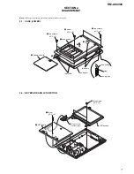
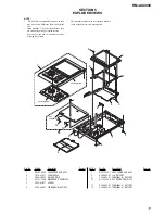
Page 7: ...y procedure in the numerical order given 2 1 CASE LOWER case upper case lower claw 1 6 3 two screws P 2 6 5 two screws P 2 6 4 screw P 2 6 2 battery case lid 7 case lower case upper two claws two claws 3 1 screw P 2 6 5 LCD section 4 two screws P 2 6 2 KEY board two piece PWB connector plug ...

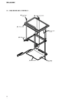
Page 8: ...8 RM AX4000 2 3 MAIN BOARD AND LCD MODULE 5 two screws P 2 6 1 flexible board CN2 2 flat type wire CN1 6 PWB holder 7 LCD module 3 two screws P 2 6 4 MAIN board ...

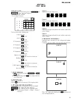
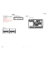
Page 9: ...tern 3 Illuminates each segment key and the clock one line at a time in the order of Pattern 1 Pattern 4 Illuminates each segment key and the clock one line at a time in the order of Pattern 2 4 Alignment test and adjustment Perform the same operation as for the setting mode alignment correction The display becomes as follows Press points 1 to 3 in this order SECTION 3 TEST MODE CONTRAST 2 1 3 5 4...

Page 10: ...ration is invalid when more than one button is pressed at the same time 2 After all the buttons are checked OK appears at the title 3 Press the OK button to proceed to the LEARN signal reception circuit check 7 LEARN signal reception circuit check 1 Press the CHANNEL button to activate the learning circuit for 10 seconds and learning start When learning is complete OK appears at the title Press th...

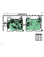
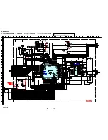
Page 11: ...acted from the conductor side Pattern from the side which enables seeing The other layers patterns are not indicated Caution Pattern face side Parts on the pattern face side seen from Side B the pattern face are indicated Parts face side Parts on the parts face side seen from Side A the parts face are indicated 1 IC1 qg PI21 OSC I 2 IC1 qs PI23 OSC I 50 0 ns 2 6 Vp p 1V DIV 40 ns DIV 30 5us 3 7 Vp...

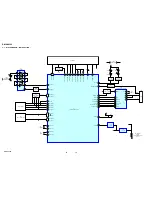
Page 12: ...23 OSC_I P121 OSC_I P122 OSC_O 75 41 61 62 63 64 65 4 68 29 2 9 30 37 24 26 TOUCH PANEL XR YU XL YO KEY S2 S3 S5 S29 S31 11 X2 32 768KHz 12 14 X1 20MHz 15 79 78 77 76 73 72 71 70 47 44 Q12 LCD CONTROL LCD MODULE 5 8 P16 IR_O 48 P30 INT1 VBUS_I 46 5V P56 VBUS_O 57 P57 CS_O 58 P11 USBTX_O 54 P11 USBRX_I 53 P12 S_O 52 P32 USB_SM_INT_I 40 P06 T1011 T001 38 P15 BZ_O 49 RESET_I 10 Q13 LED DRIVER Q14 LED...

Page 13: ... 4 LED4 B 5 LED5 B 4 Q4 B 6 Q6 B 6 Q7 B 12 Q8 B 12 Q9 B 12 Q10 B 13 Q12 C 9 Q13 B 3 Q14 B 5 Q15 C 5 IC1 SYSTEM CONTROLLER can not be replaced individually Replace it with MAIN board assembly for service IC3 IC6 IC1 IC2A IC4 KEY BOARD DRY BATTERY SIZE AA IEC DESIGNATION R6 4PCS 6V 1 867 249 11 VIN VOUT VSS SEND INFRARED RAYS SEND INFRARED RAYS RECEIVED INFRARED RAYS MAIN BOARD SIDE A USB 1 5 1 867 ...

Page 14: ...5V GND 2SA1037AKT146Q 16V FLSO FLSI RST 47K 47K 47K 1K 47K 47K 47K 47K 47K 100k 100k 100k 100k 100 0 47k 1k 22k 10 10 10 10 470 470 470 4 7k 4 7k 4 7k 4 7k 4 7k 4 7k 4 7k 2 2M 68k 10k 1 5k 4 7k 16V 16V FLMD0 MAZT082H08S0 560 0 47K MAZW068H0LS0 4 7k BUZZER 470k 32 768KHz 39K 39K UDZSTE 176 2B 22 2 2 22 2 2 47k BC857CWT1G 1SS400 1k BC857CWT1G BC857CWT1G IC XC6201P502PR 10K 470k 100k 1M DIODE SID307B...

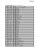
Page 15: ...upply 5V 21 P60 SCL0 I Connected to 5V 22 P61 SDA0 I Connected to 5V 23 P62 EXSCL0 I Connected to 5V 24 P63 KEYS_O O Key scan output 25 P33 INTP4 I Connected to 5V 26 P64 KEYS_O O Key scan output 27 P65 KEYS_O O Key scan output 28 P66 KEYS_O O Key scan output 29 P67 KEYS_O O Key scan output 30 P77 KEYD_I I Key data input 31 P76 KEYD_I I Key data input 32 P75 KEYD_I I Key data input 33 P74 KEYD_I I...

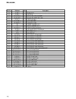
Page 16: ...gnal input 63 P25 TPXL_I I TOUCH PANEL XL signal input 64 P24 TPYD_I I TOUCH PANEL YD signal input 65 P23 TPSS_O O TOUCH PANEL control signal output 66 P22 TPSS_O O TOUCH PANEL control signal output 67 P21 TPSS_O O TOUCH PANEL control signal output 68 P20 TPSS_O O TOUCH PANEL control signal output 69 P130 TPSS_O O TOUCH PANEL control signal output not used 70 P04 LCDCONT_O O LCD_contrast signal ou...

Page 17: ...SSY 2 1 479 455 11 LCD MODULE 3 2 596 422 01 HOLDER PWB 4 A 1133 785 A MAIN BOARD COMPLETE 5 3 254 070 11 SCREW 6 2 596 426 01 TERMINAL B BATTERY Ref No Part No Description Remark The mechanical parts with no reference number in the exploded views are not supplied 7 X 2055 589 1 CASE LOWER SUB ASSY 8 2 596 428 01 LID BATTERY 9 2 596 425 01 TERMINAL A BATTERY 10 A 1133 784 A KEY BOARD COMPLETE 11 2...

Page 18: ...6 11 CERAMIC CHIP 0 1uF 10 16V C721 1 107 826 11 CERAMIC CHIP 0 1uF 10 16V C722 1 107 826 11 CERAMIC CHIP 0 1uF 10 16V C723 1 137 910 11 TANTAL CHIP 10uF 20 16V C724 1 115 416 11 CERAMIC CHIP 0 001uF 5 25V C725 1 162 916 11 CERAMIC CHIP 12PF 5 50V C726 1 162 970 11 CERAMIC CHIP 0 01uF 10 25V C727 1 115 416 11 CERAMIC CHIP 0 001uF 5 25V C728 1 115 416 11 CERAMIC CHIP 0 001uF 5 25V C729 1 162 916 11...

Page 19: ... RES CHIP 10 5 1 8W R36 1 216 150 91 RES CHIP 10 5 1 8W R37 1 216 817 11 METAL CHIP 470 5 1 10W R38 1 216 817 11 METAL CHIP 470 5 1 10W R39 1 216 833 11 METAL CHIP 10K 5 1 10W R40 1 216 837 11 METAL CHIP 22K 5 1 10W R41 1 216 829 11 METAL CHIP 4 7K 5 1 10W R42 1 216 861 11 METAL CHIP 2 2M 5 1 10W R43 1 216 843 11 METAL CHIP 68K 5 1 10W R44 1 216 841 11 METAL CHIP 47K 5 1 10W R45 1 216 817 11 METAL...

Page 20: ...STORY Clicking the version allows you to jump to the revised page Also clicking the version at the upper right on the revised page allows you to jump to the next revised page Ver Date Description of Revision 1 0 2005 08 New ...

Reviews: