PRS-T2
3
NOTE THE EACH BOARDS REPAIRING
The mount parts on each boards installed in this set cannot ex-
change with single. When the each boards are damaged, exchange
the entire mounted board.
NOTE OF REPLACING THE COMPLETE MAIN BOARD
OR CHASSIS ASSY
Please do the following work when you exchange complete MAIN
board or CHASSIS ASSY.
Note:
ELEMENT INK INDICATOR 6inch is included in CHASSIS
ASSY.
• REWRITING
THE
LUT:
Refer to “10. Update Waveform” on page 11.
• Write SP1 paramenter
fi
le:
Refer to “11. Update SP1 Parameters” on page 13.
• Write
VCOM:
Refer to “16. Write VCOM” on page 14.
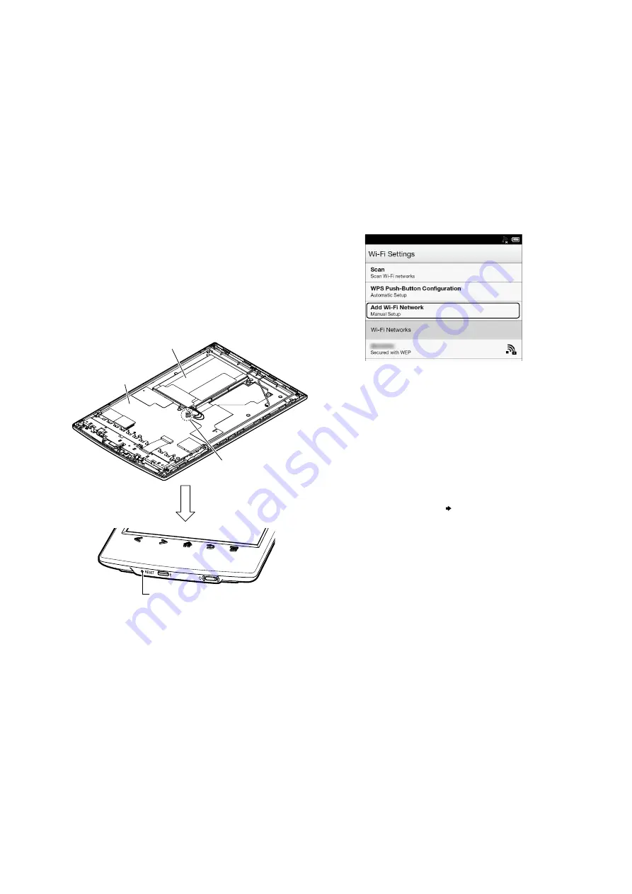
ABOUT THE LEAD WIRE OF BATTERY ASSY (BAT1)
Con
fi
rm the operation after pressing the button of the main unit
bottom without fail when soldering the BATTERY ASSY (BAT1)
to the MAIN board.
MAIN board
soldering
battery assy (BAT1)
[RESET] button
NOTE OF REPLACING THE WLAN ANTENNA
Please do the following work when you exchange WLAN AN-
TENNA.
Manually setting a Wi-Fi connection
You can set up a Wi-Fi network connection manually
by inputting the required information for connection.
Make sure to turn on [Wi-Fi] and tap [Wi-Fi Settings] on
the [Wireless Network Settings] screen. Alternatively,
you can turn on [Wi-Fi] by tapping the status bar and
tapping [Wi-Fi Settings].
1
Tap [Add Wi-Fi Network].
2
Tap [Manual Registration].
3
Tap the [SSID] input area and type in using the
on-screen keyboard.
4
Tap the [Security Method] menu (the default
value is [Open]), and then tap the supported
security type.
5
Tap the [Password] input area and type in your
password using the on-screen keyboard, and
then tap [Done] [Save].
6
Tap the saved network SSID in the [Wi-Fi
Networks] list on the [Wi-Fi Settings] screen.
7
If prompted for a password, tap the input area
and type in the password using the on-screen
keyboard.
8
Tap [Connect].
The Reader connects to the Wi-Fi network.
The Wi-Fi connection status is displayed in the
status bar.
SECTION 1
SERVICING NOTES


