


1-3
12
Hookups and Settings
Hooking Up the Recorder
Follow steps 1 to 7 to hook up and adjust the settings of the recorder.
b
Notes
• Plug cords securely to prevent unwanted noise.
• Refer to the instructions supplied with the components to be connected.
• You cannot connect this recorder to a TV that does not have a SCART or video input jack.
• Be sure to disconnect the mains lead of each component before connecting.
Step 1: Unpacking
Check that you have the following items:
• Mains lead (1)
• Aerial cable (1)
• Remote commander (remote) (1)
• R6 (size AA) batteries (2)
13
H
ook
up
s
and
Se
tti
n
gs
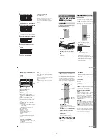
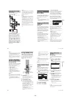
Step 2: Connecting the Aerial Cable
Connect the aerial cable by following the steps below. Do not connect the mains lead until you reach
“Step 5: Connecting the Mains Lead” on page 18.
1
Disconnect the aerial cable from your TV and connect it to AERIAL IN on the rear panel of the
recorder.
2
Connect AERIAL OUT of the recorder to the aerial input of your TV, using the supplied aerial
cable.
AERIAL
~
AC IN
IN
OUT
COMPONENT
VIDEO OUT
PB/
CB
Y
PR/
CR
LINE
2
OUT
LINE
4
IN
LINE 1 - TV
LINE 3 /
DECODER
VIDEO
-AUDIO
S VIDEO
R
L
VIDEO
-AUDIO
S VIDEO
R
L
DIGITAL
OUT
HDMI OUT
COAXIAL
OPTICAL
PCM/DTS/MPEG/DOLBY DIGITAL
AERIAL
IN
OUT
DVD recorder
TV
to AERIAL OUT
to AERIAL IN
Aerial cable (supplied)
: Signal flow
14
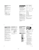
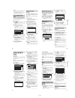
Step 3: Connecting the Video Cords/HDMI Cords
Select one of the following patterns
A
through
E
, according to the input jack on your TV monitor,
projector, or AV amplifier (receiver). This will enable you to view pictures.
A
Connecting to a SCART input jack
When you set “Line1 Output” to “S Video” or “RGB” in “Easy Setup” (page 22), use a SCART cord that
conforms to the selected signal.
B
Connecting to a video input jack
You will enjoy standard quality images.
C
Connecting to an S VIDEO input jack
You will enjoy high quality images.
D
Connecting to component video input jacks (Y, P
B
/C
B
, P
R
/C
R
)
You will enjoy accurate colour reproduction and high quality images.
If your TV accepts progressive 525p/625p format signals, you must use this connection and set
“Component Out” in “Video” setup to “On” (page 88). Then press PROGRESSIVE on the remote to send
progressive video signals. For details, see “Using the PROGRESSIVE button” on page 16.
E
Connecting to an HDMI input jack
Use a certified HDMI cord (not supplied) to enjoy high quality digital picture and sound through the
HDMI OUT jack.
15
H
ook
up
s
and
Se
tti
n
gs
When playing “wide screen” images
Some recorded images may not fit your TV
screen. To change the picture size, see page 87.
If you are connecting to a VCR
Connect your VCR to the LINE 3/DECODER
jack on the recorder (page 23).
b
Notes
• Do not connect more than one type of video cord
between the recorder and your TV at the same time.
• You cannot use the PROGRESSIVE button with the
connections
B
and
C
.
• When you connect the recorder to your TV via the
SCART jacks, the TV’s input source is set to the
recorder automatically when you start playback. If
necessary, press
t
TV/VIDEO to return the input to
the TV.
• For correct SMARTLINK connection, you will need a
SCART cord that has the full 21 pins. Refer to your
TV’s instruction manual as well for this connection.
• If you connect this recorder to a TV with SMARTLINK,
set “Line1 Output” to “Video” in “Easy Setup.”
• You cannot connect the HDMI OUT jack (connection
E
) to DVI jacks that are not HDCP compliant (e.g.,
DVI jacks on PC displays).
* This DVD recorder is based on version 1.1 of High-
Definition Multimedia Interface Specifications.
This DVD recorder incorporates High-Definition
Multimedia Interface (HDMI™) technology.
HDMI, the HDMI logo and High-Definition
Multimedia Interface are trademarks or registered
trademarks of HDMI Licensing LLC.
AERIAL
~
AC IN
IN
OUT
COMPONENT
VIDEO OUT
PB/
CB
Y
PR/
CR
LINE
2
OUT
LINE
4
IN
LINE 1 - TV
LINE 3 /
DECODER
VIDEO
-AUDIO
S VIDEO
R
L
VIDEO
-AUDIO
S VIDEO
R
L
DIGITAL
OUT
HDMI OUT
COAXIAL
OPTICAL
PCM/DTS/MPEG/DOLBY DIGITAL
VIDEO
AUDIO
INPUT
L
R
INPUT
S VIDEO
P
R
/C
R
P
B
/C
B
Y
COMPONENT
VIDEO IN
IN
C
B
D
A
E
Audio/video cord
(not supplied)
Component video
cord (not supplied)
(yellow)
TV, projector, or AV
amplifier (receiver)
TV, projector, or AV
amplifier (receiver)
(green)
S-video cord
(not supplied)
TV, projector, or AV
amplifier (receiver)
(red)
(blue)
(green)
(blue)
(red)
: Signal flow
to COMPONENT
VIDEO OUT
to LINE 2 OUT (VIDEO)
to LINE 2 OUT (S VIDEO)
SCART cord
(not supplied)
To
i
LINE 1 – TV
DVD recorder
TV
TV, projector, or AV
amplifier (receiver)
to HDMI OUT
HDMI cord
(not supplied)
,
continued
Summary of Contents for RDR-HX1010
Page 6: ...MEMO 6 ...
Page 98: ...MEMO 5 10E ...


