13
Name and Function of Parts
Name and Function of Parts
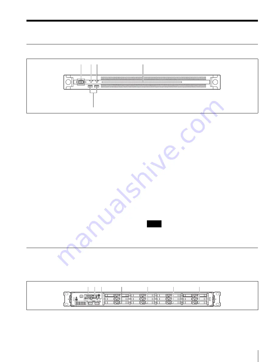
Front View
a
On/Standby button and indicator
Switches the unit on/off (standby state). Connecting the
power cord places the unit in standby state, and the
indicator turns on red. Pressing the On/Standby button
while in standby state turns on the unit and the indicator
turns on green. Pressing and holding the On/Standby
button for two seconds switches the unit to standby state,
and the indicator changes to red. To turn the unit on again
after switching from On state to standby state, when the
indicator is red, press and hold the On/Standby button for
three seconds or longer. The indicator goes out when the
power cord is disconnected.
b
SYSTEM indicator
Indicates the status of the unit.
Green:
Operating normally
Flashing green (once per second):
System is booting or
transitioning to standby state.
Flashing orange (once per second):
A warning has been
generated.
High-speed flashing read (four times per second):
An
error has occurred.
c
ACCESS indicator
Indicates the access status to storage.
Off:
Not accessing storage
Blue:
Accessing storage
d
Front panel LED
Turns on according to settings in the web application. The
LED is configured using [001: LINE LED] in the
[Settings] page on the Maintenance screen.
e
USB connectors (front panel)
Connects to a keyboard and mouse for initializing the unit.
USB devices not described in this document are not supported.
• Both USB ports on the front panel support power delivery (900 mA).
• Use SuperSpeed USB cables.
Front View (Panel Removed)
When the SYSTEM indicator or web application indicates
an error, you can remove the front panel to check the status
of the hardware components.
To remove the front panel, loosen the screws on the left
and right sides and pull the panel towards you.
a
FAN indicators
If any of the fans fail, the corresponding fan indicator turns
on red.
b
POWER indicators
If either of the AC power supply units fail, the
corresponding indicator turns on red.
1
2 3
4
5
Notes
1
2 3
4
4
4
4


