background image

PRS-T1

11

14. Write VCOM

In this mode, the VCOM voltage can be rewritten.
The VCOM voltage for INK INDICATOR 6inch ELEMENT  is 
individually different.
Therefor, when replacing the complete MAIN board or CHASSIS 
ASSY (including INK INDICATOR 6inch ELEMENT) you need 
to rewrite the VCOM voltage.

Procedure:

1. The VCOM voltage con

fi

 rm method is different according to 

replaced parts.


When the complete MAIN board is replaced:


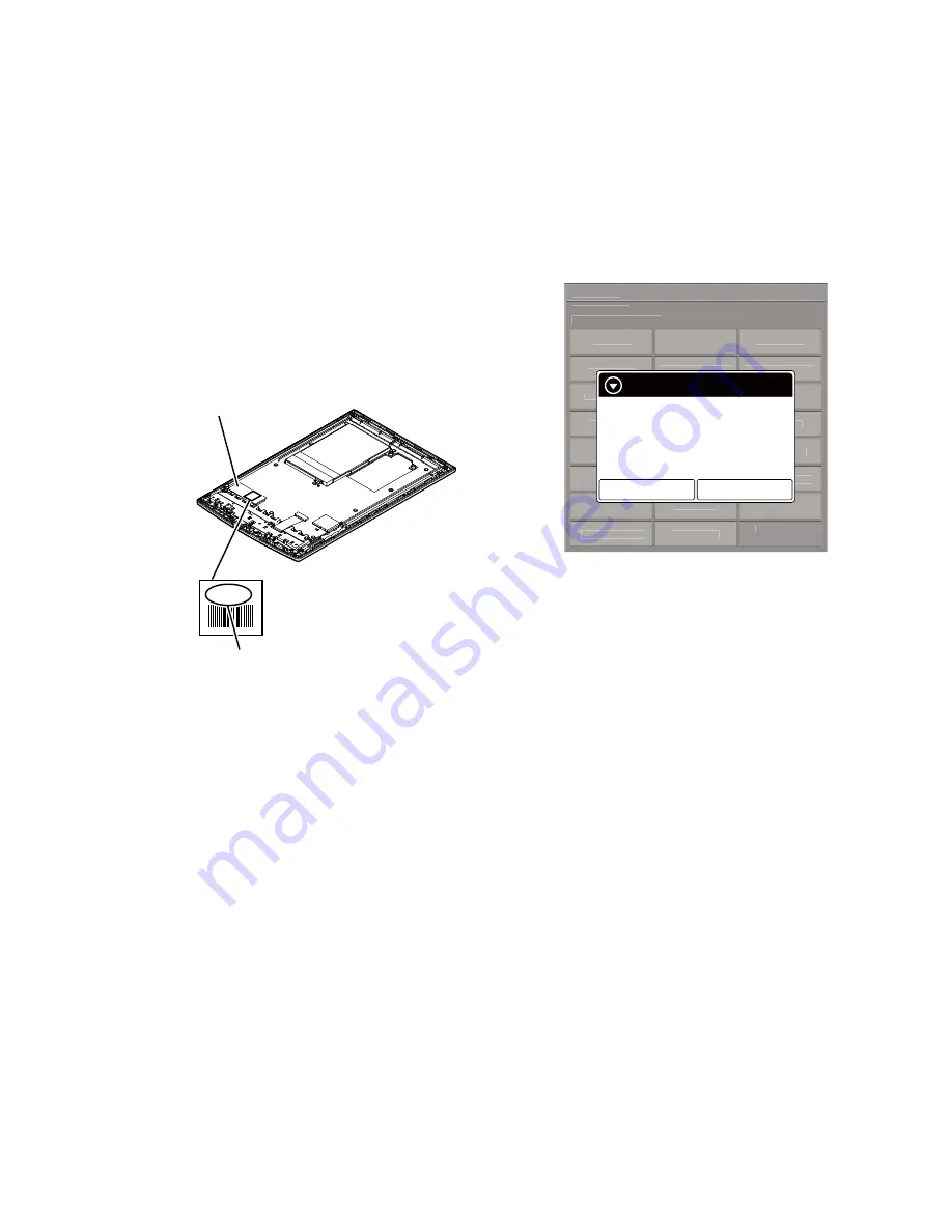
Disassemble this unit until the VCOM voltage is seen (Refer to 
“2. DISASSEMBLY” (pages 3 to 7)), and con

fi

 rm the VCOM 

voltage referring to the 

fi

 gure below. Record the con

fi

 rmed the 

VCOM voltage by taking the memo etc..

Flexible board of INK 
INDICATOR 6inch ELEMENT

VCOM voltage

-2.03


When the CHASSIS ASSY (including INK INDICATOR 
6inch ELEMENT) is replaced:

 Con

fi

 rm the VCOM voltage described on the label of new 

CHASSIS ASSY (including INK INDICATOR 6inch ELE-
MENT). Record the con

fi

 rmed the VCOM voltage by taking 

the memo etc..

2.  Replace complete MAIN board or CHASSIS ASSY (including 

INK INDICATOR 6inch ELEMENT) for new parts, and as-
semble this unit.

3. Make the text 

fi

 le on PC, and write the VCOM voltage con-

fi

 rmed in step 1.

Note 1:

 The VCOM voltage is described by the unit of mV that omits 

minus (Example: Write “2030” when it is printed on the label as 
“–2.03 V”).

4.  Press the [

1

] key to turn the power on.

5. Con

fi

 rm the HOME menu was completely displayed, and con-

nect this unit to PC by the USB cable (MICRO B).

6. Con

fi

 rm the USB connection screen displayed, and touch the 

“Data Transfer Mode”.

7. Con

fi

 rm the “READER” drive of this unit is recognized.

8.  Make the following folder under the “READER” drive of this 

unit.

 /testmode/data/

9. Copy the text 

fi

 le made in step 3 to the “data” folder made in 

step 8. Then, change the 

fi

 le name to “Vcom.dt”.

10. Copy the 

fi

 le for the test mode from PC to directly under the 

“READER” drive of this unit.

Note 2:

 When the 

fi

 le for the test mode already exists directly under the 

“READER” drive of this unit, the 

fi

 le for the test mode need not 

be newly copied.

11.  Remove this unit and USB cable (MICRO B) from PC.
12. Enter the test mode (Refer to “HOW TO ENTER THE TEST 

MODE” (page 8)).

13. Touch the “Write VCOM” in the test mode menu, and con

fi

 rm 

current (unrenewed) VCOM voltage is displayed (Example: 
-1854 mV in the 

fi

 gure below).

@Test Mode

Version: X.X.X
Target storage: Internal

Test Panal

Update Waveform

IR-LED Level

Drawing with

Points

Reset Device Lock

Check 3G Module

TP Coordinate

Power Off

Check User

History

Test All Key

Log Extact 1

Switch ADB

Test Battery Life

Check

Temperature

Fake MoAkey

Version

Confirmation

Write VCOM

Reboot (Normal)

Check Battery

WWAN ON

Reboot (Recovery)

Factory Initialize

WWAN OFF

Log Extact 2

(Flush)

Write VCOM

Status: 1854mV

Whould you like to write?
New value: 2030mV

Yes

No

(Example of displaying current

 (unrenewed) VCOM voltage)

14. Touch the “Yes”, it starts rewriting the VCOM voltage.
15. Con

fi

 rm the VCOM voltage has been updated.

15. WWAN ON

This mode is not used in servicing.

16. WWAN OFF

This mode is not used in servicing.

17. IR-LED Level

This mode is not used in servicing.

18. Check 3G Module

This mode is not used in servicing.

19. Check User History

This mode is not used in servicing.

20. Switch ADB

This mode is not used in servicing.

21. Fake MoAkey

This mode is not used in servicing.

22. Reboot (Normal)

This mode is not used in servicing.

23. Reboot (Recovery)

This mode is not used in servicing.

24. Log Extact 2 (Flush)

This mode is not used in servicing.

Summary of Contents for PRS-T1

Page 1: ...file size and format it may not be possible to view display play some data Books EPUB files epub EPUB OPS version 2 0 supported PDF files pdf Support is based on the PDF 1 6 specification Text files txt Audio MP3 files mp3 The following specifications should be met in order to import an MP3 file Bit rate 8 to 320 kbps Sampling frequency 8 to 48 kHz File must be unsecured AAC files mp4 m4a Raw AAC ...

Page 2: ...n the Wi Fi Networks list on the Wi Fi Settings screen 7 If prompted for a password tap the input area and type in the password using the on screen keyboard 8 Tap Connect The Reader connects to the Wi Fi network The Wi Fi connection status is displayed in the status bar System Requirements The Reader software will work with the following operating systems Operating System Details Microsoft Windows...

Page 3: ...MBLY This set can be disassembled in the order shown below 2 1 DISASSEMBLY FLOW SET 2 2 CASE REAR ASSY Page 4 2 3 MAIN BOARD Page 5 2 4 CASE FRONT ASSY Page 6 2 5 BATTERY ASSY BAT1 Page 7 2 6 CHASSIS ASSY IIE1 JACK BOARD Page 7 ...

Page 4: ... direction to remove claws of case rear assy JIG When disassembling the set use the following jig Part No 9 913 402 33 Tool for Disassembly 7 case rear assy Rear bottom view Rear bottom view 3 Insert the jig in the gap between case rear assy and case front assy Then slide it to arrow direction to remove claws of case rear assy Right side case rear assy case front assy Left side case rear assy case...

Page 5: ... PWB 0 MAIN board copper leaf PWB 5HDU ERWWRP YLHZ 5 FPC M J5047 FPC1 6 element INK indicator flexible printed board 7 screw M1 4 u 1 6 8 screw M1 4 u L2 8 seven screws M1 4 u L2 white red black battery assy BAT1 8 three screws M1 4 u L2 Note 1 Please spread a sheet under a unit not to injure case front 4 Remove three solders of wire of battery assy BAT1 Note 2 When soldering refer to ABOUT THE LE...

Page 6: ...rrow B 6 Remove six claws in order of the arrow C 8 case front assy 7 1 sheet AL 2 WLAN antenna connector 3 three tapping screws P2 3 three tapping screws P2 OK NG sheet AL MAIN board MAIN board WLAN antenna conductor part without film film part N aQteQQa wire VettiQJ Note Please spread a sheet under a unit not to injure case front ...

Page 7: ...e case front 4 Remove three solders of wire of battery assy BAT1 Note 2 When soldering refer to ABOUT THE LEAD WIRE OF BATTERY ASSY BAT1 page 2 Front bottom view 1 three screws PWH 1 three screws PWH 2 light guide 3 three screws M1 4 u L2 4 claw 5 Pull out FPC M J5047 FPC1 from the slit slit 6 chassis assy IIE1 7 FPC M J5047 FPC1 FPC M J5047 FPC1 convex part 8 JACK board JACK board Note When insta...

Page 8: ...etely displayed 2 Connect this unit to PC by the USB cable MICRO B 3 Confirm the USB connection screen displayed and touch the Data Transfer Mode 4 Confirm the READER drive of this unit is recognized 5 Delete the file for the test mode from directly under the READER drive of this unit 6 Remove this unit and USB cable MICRO B from PC 7 Confirm the HOME menu was completely displayed and press the ke...

Page 9: ... according to replaced parts When the complete MAIN board is replaced Disassemble this unit until the FPL lot number and TFT vender are seen Refer to 2 DISASSEMBLY pages 3 to 7 and confirm the FPL lot number and TFT vender referring to the figure below Record the confirmed the FPL lot number and TFT vender by taking the memo etc FPL lot number Flexible board of INK INDICATOR 6inch ELEMENT E4KR28C0...

Page 10: ...ze WWAN OFF Log Extact 2 Flush Update waveform Current 0000112344567789 Would you like to update Yes No Example of displaying current unrenewed LUT version 16 Touch the Yes it starts rewriting LUT version 17 After about 10 seconds screen changes into all white 18 Press RESET key and reboot this unit 19 Enter the test mode again and confirm LUT version has been updated 10 Reset Device Lock When the...

Page 11: ...ive of this unit testmode data 9 Copy the text file made in step 3 to the data folder made in step 8 Then change the file name to Vcom dt 10 Copy the file for the test mode from PC to directly under the READER drive of this unit Note 2 When the file for the test mode already exists directly under the READER drive of this unit the file for the test mode need not be newly copied 11 Remove this unit ...

Page 12: ...1 916 01 SHEET CARD LED for WHITE Ref No Part No Description Remark Ref No Part No Description Remark Note XX and X mean standardized parts so they may have some difference from the original one Items marked are not stocked since they are seldom required for routine ser vice Some delay should be anticipated when ordering these items The mechanical parts with no reference number in the exploded vie...

Page 13: ... FRONT ASSY RED ANT1 1 754 788 11 ANTENNA WLAN BAT1 A 1832 983 A BATTERY ASSY Ref No Part No Description Remark Ref No Part No Description Remark chassis section ANT1 51 52 53 54 BAT1 52 Note 1 Confirm the operation after pressing the button of the main unit bottom without fail when soldering the BATTERY ASSY BAT1 to the MAIN board Note 2 When replacing the WLAN antenna ANT1 refer to NOTE OF REPLA...

Page 14: ...M1 4X1 6 107 4 287 943 01 LEAF PWB COPPER 108 4 408 115 01 SHEET 4X3 ADHESIVE FPC1 1 884 637 11 FPC M J5047 IIE1 A 1832 982 A CHASSIS ASSY Including INK INDICATOR 6 inch ELEMENT Ref No Part No Description Remark Ref No Part No Description Remark FPC1 101 IIE1 102 103 104 105 106 107 103 103 103 108 101 Note When replacing the MAIN board or CHASSIS ASSY IIE1 refer to NOTE OF REPLACING THE COMPLETE ...

Page 15: ... 610 12 QUICK START GUIDE PAPER ENGLISH FRENCH 4 288 610 22 QUICK START GUIDE PAPER GERMAN DUTCH AEP UK 4 288 610 32 QUICK START GUIDE PAPER SPANISH ITALIAN AEP UK 4 288 610 41 QUICK START GUIDE PAPER FINNISH SWEDISH AEP UK 4 288 610 51 QUICK START GUIDE PAPER DANISH NORWEGIAN AEP UK X 2582 530 1 STYLUS ASSY Stylus ...

Page 16: ...HISTORY Checking the version allows you to jump to the revised page Also clicking the version at the top of the revised page allows you to jump to the next revised page Ver Date Description of Revision 1 0 2011 09 New ...

Reviews: