7
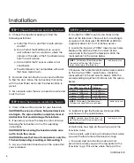
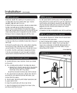
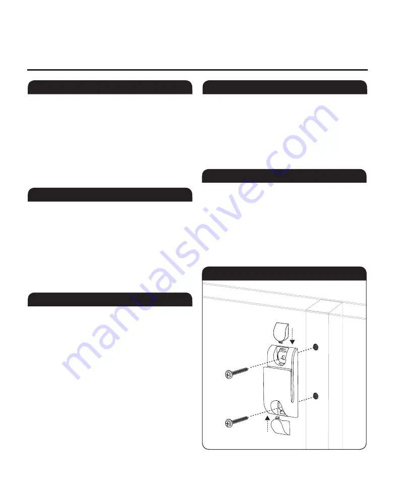
G. use your electric drill to screw in the lag bolts to
firmly attach the wall hook to the wall. For wood stud
construction, you will be screwing the lag bolts into
the stud. For concrete walls, you will be screwing the
lag bolts into the anchors. Be careful not to over-
tighten the lag bolts.
H. Replace the top and bottom caps on the wall hook.
Installation
(cOnTInuED)
STEP 3:
Mark the bottom screw location
STEP 4:
Attach wall hook to the wall
STEP 4
(continued)
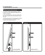
STEPS 3 & 4
STEP 5:
Attach TV harness to television
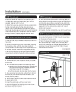
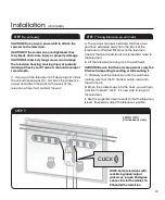
A. Remove the top and bottom caps from the wall
hook (A).
B. Place the wall hook on the wall surface, aligning
the top screw hole with the top screw location
you’ve marked. If necessary, use a carpenter’s level
to confirm that the wall hook is aligned vertically.
c. Make a small pencil mark through the bottom
screw hole to indicate the bottom screw location.
A. Locate the two screw location marks you made
on the wall.
B. For concrete walls, perform the following steps:
a. Attach the 1/2-inch masonry bit to your electric
drill (hammer drill recommended) and drill
holes two inches (50 mm) deep.
b. Set the concrete anchors (Q) into the holes.
c. For wood stud construction, attach the 1/8-inch
wood bit to your electric drill and drill holes two
inches (50 mm) deep.
D. For all walls, attach the #2 Phillips head driver bit
to your electric drill.
E. Align the wall hook with the screw holes.
F. Insert the lag bolts (P) through the holes in the
wall hook and into the wall.
STEP 2
(continued)
television meets the wall stud. If necessary, use
a carpenter’s level to confirm that your mark is
properly aligned with the stud.
K. Mark the top screw location. Measure down from
the Top center Mark by the Top Screw Distance
(Line 3 in your calculation on the previous page)
and make another pencil mark on the wall. For wood
stud construction, use a carpenter’s level to confirm
that your mark is properly aligned with the stud.
A. Locate the top pair of “VESA” mount screw holes
on the back of the television.
B. The TV harness (B) includes a pair of mounting
bars connected by a cable. The mounting bars
have holes indicated at 100, 200, 300 and 400 mm
spacing. Line up the bars with the “VESA” mount
screw holes that match.
cOnTInuED
➔
WAll / sTud

