


– 17 –
SECTION 3
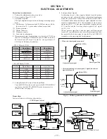
ELECTRICAL ADJUSTMENTS
Precautions on adjustment:
1. Perform the adjustment in the given order.
2. Power supply voltage: DC 9.0 V
3. Equipment required
Electrical adjustment requires the following measuring equip-
ment.
(1)
Oscilloscope: 2 phenomena, band 30 MHz or more, with de-
lay mode (use 10 : 1 probe unless otherwise specified)
(2)
Pattern generator
(3)
Digital voltmeter
(4)
Frequency counter
(5)
Connector for adjustment
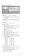
4. Measurement points for adjustment are located at CN102 on
the YM-11P board for VIDEO block, and at CN404 on the RG-
46P board for LCD block. The pin No. and signal name of
CN102 and CN404 are listed below.
• YM-11P Board, CN102
• RG-46P Board, CN404
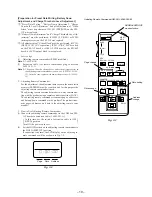
5. Setting Method of External Video Input Mode
Turn the POWER switch on, and operate the SEL/PUSH EXEC
jog dial, so that the EXT. VIDEO IN mode becomes active.
(Refer to item 9 on page 22)
Preparation:
Connect all electrical blocks as shown below.
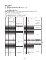
Pin No.
Signal Name
1
T.GND
2
FREE RUN ON
3
LANC SIG
4
V IN
5
CHK BL+B
Pin No.
Signal Name
6
HAFC
7
POWER SW
8
Y
9
VCLVL
10
SC OUT
Pin No.
Signal Name
1
GND
2
EAC OFF
3
HP L
4
G OUT
5
HP R
Pin No.
Signal Name
6
B OUT
7
HP RET
8
R OUT
9
PCO
10
N.C
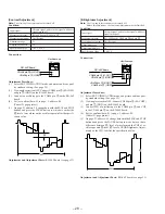
6. Setting up Input Signals
In adjusting this set, video signals obtained from the pattern
generator are used, and therefore these video output signals must
satisfy the specification. Connect the oscilloscope to the VIDEO
IN terminal, and confirm that the sync signal amplitude of video
signals is approximately 0.3 V, the amplitude of video part is
approximately 0.7 V, burst signal amplitude is approximately
0.3 V and flat, and the level ratio of burst signal to “red” signal
is 0.30 : 0.66.
Where “chroma signal, and color bar signal with burst signal
turned off” is specified in the text, enter chroma signal and color
bar signal of which burst signal is turned off to the VIDEO IN
terminal as video input signals for adjustment.
S702
VIDEO
SG
AUDIO
SG
DC 9.0 V
S703
SA-52P
FFC
CN903
CN401
CN405
CN404
RG-46P
LCD
LCD
FP-29
CN902
CN102
CN301
S701
SW-312P
YM-11P
J101
J301
CN406
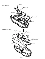
IF BOX Upper Cabinet
Back Light Unit
Headphone L,R load 16
Ω
×
2
suitable
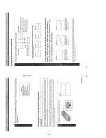
Fig. 3-1. Pattern generator's color bar signals
White (100%)
approx.
0.3 V
approx.
0.7 V
approx.
0.3 V
• When color bar signals are entered
Red
Burst signal (flat)
Horizontal sync signal
• Chroma signal and color bar signal (Y signal) when burst
signal is turned off
No burst signal
Horizontal sync signal
approx.
0.7 V
approx.
0.3 V
White (100%)
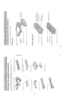
Summary of Contents for PLM-A55E
Page 1: ...SERVICE MANUAL GLASSTRON AEP Model UK Model SPECIFICATIONS PLM A55E 9 928 101 31 ...
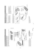
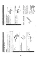
Page 3: ... 3 SECTION 1 GENERAL This section is extracted from instruction manual ...
Page 4: ... 4 ...
Page 5: ... 5 ...
Page 6: ... 6 ...
Page 7: ... 7 ...
Page 8: ... 8 ...
Page 9: ... 9 ...
Page 10: ... 10 ...
Page 11: ... 11 ...
Page 12: ... 12 ...
Page 13: ... 13 ...
Page 14: ... 14 ...


